Cable truck to camper best practices

Defulmmt

Advanced Member
Joined
Sep 30, 2022
Messages
36
Location
Montana
I’m about to replace the 10/2 wire from the truck battery to the camper battery. I have these components

ATC 2021 Panther
2019 Superduty (I don’t believe that the truck has a smart alternator)
6 awg cable (2 conductors)
(2) 80 amp circuit breakers for each end of 6 awg cable
(1) 30 amp circuit breaker for 160 watt roof top solar
Renogy 50amp dcdc with mppt controller
Battle Born 100amp 12v

I can purchase 25’ of carflex 3/4 inch nonmetallic conduit to run the cables at a reasonable price. Is this recommended to protect the cables from weather and road conditions? The existing cable is interior use 10/2 romex. One thought I have is that if the 6 awg cable causes too much voltage drop I could fish a 4 awg cable through the conduit fairly easily. Two 6awg cables fit easily in 3/4 inch carflex, but I’m not sure about 4 awg cables. Is conduit to protect the wiring necessary? I’d like this to last 10 years or more.

I see that the existing 10/2 cable ve- is connected to the same chassis point as the ve- cable from the battery. Is this the preferred grounding point? I assumed I’d run the cable to the negative battery post.

My first thought was to install the 80 amp breakers close to each battery. That would place the breaker between the dcdc and the camper battery on a short cable run, probably less than 2 feet. My current thought is placing it before the dcdc based on what I’ve learned here ( in fact, everything I know about this upgrade I’ve learned here).

Any insights on best practices will be appreciated. And thanks to the masters of electrons that share such good advice on this forum.
 
Hello Defulmmt
I have done pretty much same 6awg but not in conduit. I think it’s a 60amp circuit breaker up at the battery under hood. Another circuit breaker just before the positive terminal on the lithium battery in camper. The pos and neg go straight to the controller in the camper with in 12 inches of battery. A renogy 30 amp dcdc with the solar mppt . I used a Anderson connector out side the anchor point door on the passenger side to be able to disconnect camper from truck. Most current seen is 25 amps but battery seldom gets below 60%
I’m not an electrical expert by any means.
So can’t help with conduit. Have been very happy with wire upgrades.

Russ
 
Thanks Russ, carlon flex is probably overkill but a split wire loom to protect the cables seems appropriate.

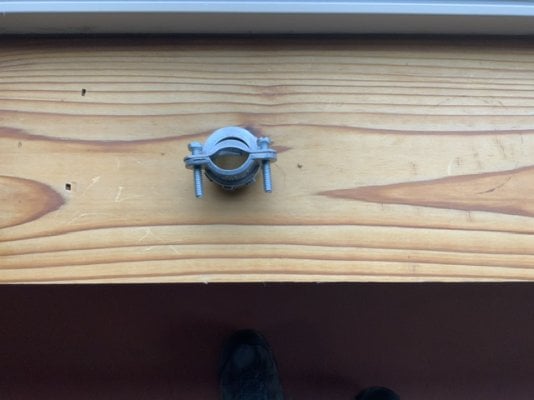
I’m currently searching for a connecter to use for protecting the cables where they penetrates the aluminum truck bed. I found a cable gland in the shop that I previously used on a junction box. It holds the cables securely and with some loctite and caulk it would probably work. There must be a better product for this, but this is what I have. Hoping someone suggests something better.
 
This is the cable gland I found in my shop. It secures two 6 awg cables. Loctite to make sure nothing comes loose, caulk to waterproof. Still searching for a more appropriate bulkhead connector.
 

Attachments

  • IMG_0193.jpeg
    IMG_0193.jpeg
    64.4 KB · Views: 44
PaulT said:
Search for "marine cable gland" . There are quite a variety from which to choose.

Paul
if you are coming in from the side of the cargo bed, a "marine cable gland" works well. My duplex #6 gauge wiring was jacketed and the 3/4" size gland was a good fit. The gland is made of plastic, so it has the advantage of being a good insulator.

https://www.amazon.com/Strain-Relief-Glands-Adjustable-Compliant/dp/B092ZMRW55/ref=asc_df_B092ZMRW55/?tag=hyprod-20&linkCode=df0&hvadid=647287837175&hvpos=&hvnetw=g&hvrand=2872124613785350199&hvpone=&hvptwo=&hvqmt=&hvdev=c&hvdvcmdl=&hvlocint=&hvlocphy=9028316&hvtargid=pla-1983896844444&psc=1
 
Thanks guys, I’ve already ordered one.

One question about them, do they provide enough strain relief or do they require the conductors to be secured to the bulkhead immediately before or after the marine cable gland.

thx,
 
When you get one of the marine glands you'll notice a ring of plastic teeth that tighten up around the wire when the outer nut is screwed down.
 
I have the marine cable gland installed. I used a hole saw to slightly enlarge the original entry point that ATC made when they installed the 10 awg. I also installed the cable gland pictured above to the cable entry hole to protect the cables from the bed metal. It appears to be a good solution although it was very difficult to access. Vic’s solution described above would have been much simpler and, as it turns out, that area appears to be well protected from road spray, mud etc. (2019 f250).

Next step is running the cables to the engine compartment. I have one question on grounding …..ATC terminated the ve- cable at the chassis where the battery ve- cable is terminated. Is it a better practical to run the ve- to the battery ve- post? This maybe a newbie question and perhaps there is absolutely no difference, but I want to get it right before I terminate the cable. Thx.
 
Defulmmt said:
… I have one question on grounding …..ATC terminated the ve- cable at the chassis where the battery ve- cable is terminated. Is it a better practical to run the ve- to the battery ve- post? This maybe a newbie question and perhaps there is absolutely no difference, but I want to get it right before I terminate the cable. Thx.

Either termination point is fine for the amount of current you are talking about as long as good practices are followed.
 
The F-150 uses a hall effect current sensor the negative battery lead for the internal battery monitoring system (BMS) which in turn controls the alternator output among other things. Connecting to the battery neg post would bypass that sensor and not let it see the actual state of the battery current draw thus altering the calculated battery SOC. The F-250 may also have a BMS from what I can see. I would use the chassis connection. They will both work though.
 
K7MDL said:
The F-150 uses a hall effect current sensor the negative battery lead for the internal battery monitoring system (BMS) which in turn controls the alternator output among other things. Connecting to the battery neg post would bypass that sensor and not let it see the actual state of the battery current draw thus altering the calculated battery SOC. The F-250 may also have a BMS from what I can see. I would use the chassis connection. They will both work though.
That’s a new one for me… really good to know!
 
K7MDL said:
The F-150 uses a hall effect current sensor the negative battery lead for the internal battery monitoring system (BMS) which in turn controls the alternator output among other things. Connecting to the battery neg post would bypass that sensor and not let it see the actual state of the battery current draw thus altering the calculated battery SOC. The F-250 may also have a BMS from what I can see. I would use the chassis connection. They will both work though.
Thanks for sharing, I had to look that one up.
 
I terminated the ve- cable in the engine compartment at the chassis ground point, ve+ at the Blue Sea CB.

Do smart alternators use the Hall effect sensor to manage alternator output?
 
I do not know what other vehicles use myself, but hall effect sensors are small and popular. I use one for my main 70A 12V ham radio shack power supply current meter. They are also used for charge and discharge current sensing in large 150VDC oil-filled pressure tolerant lithium batteries I work on used for deep submersibles. They are very reliable but I did have to replace one buried inside of one battery.
 
I’m making progress inside the camper with a new battery box (16 inch square footprint). It’s a tight fit, but I have the components installed. A little larger box would have probably been a good idea.

A couple of wiring issues have come up:

1) IIRC Tacoma Austin has a Blue Sea circuit breaker in the solar input line. Seems like a good idea particularly with the Renogy dcdc. I think if the circuit is open the dcdc wouldn’t sense a solar input and could deliver the rated charge from the alternator. Do I understand this correctly?

2) There are 10 awg wires from the battery compartment to the dc fuse panel. I don’t recall seeing a fuse on this line during the disassembly of the stock system. The loads on the panel are all fused but shouldn’t the 10 awg cable be fused. I believe 30 amps is the maximum current for a 10 awg cable. Is an in line fuse or a circuit breaker a best practice for this cable?
 
Defulmmt said:
1) IIRC Tacoma Austin has a Blue Sea circuit breaker in the solar input line. Seems like a good idea particularly with the Renogy dcdc. I think if the circuit is open the dcdc wouldn’t sense a solar input and could deliver the rated charge from the alternator. Do I understand this correctly?
The breaker for my solar panel is for when I disconnect the house battery for storage. It lets me isolate the solar panels BEFORE switching off the house battery.

I haven't used this feature remove the solar panel from the equation when driving down the road for the purpose of bumping up the charging amps from the Renogy DC to DC charger. I may do this later on in the year when the solar panel is next to useless on a dreary winter day.
 
2) There are 10 awg wires from the battery compartment to the dc fuse panel. I don’t recall seeing a fuse on this line during the disassembly of the stock system. The loads on the panel are all fused but shouldn’t the 10 awg cable be fused. I believe 30 amps is the maximum current for a 10 awg cable. Is an in line fuse or a circuit breaker a best practice for this cable?


Generally you want a fuse and/or battery disconnect as close to the battery as you can get. There are standards (RVIA for RVs, ABYC/NMEA for marine) that specify max distances allowed. Also wire size guides for current in a length of wire for specified voltage drops and insulation temperature ratings. For marine it can vary, if cable is jacketed or in conduit it is allowed to go further from the battery.

It comes down to a risk calculation - what is the chance of the wire from the battery to the first fuse or load point getting damaged and shorting, thus unleashing massive current and burning your wire and perhaps your vehicle with it?

I believe the RVIA magic number is 18 inches but I do not have the standard in front of me. In our campers the battery to fuse block wire may be close, though it seems like a bit longer in mine. Given that the wire is reasonably protected in sheathing and/or in cable harnesses in backs of cabinets, the risk of going a few inches longer seems low and I suspect FWC thinks so also. Of my 3 FWC campers, none use battery fuses or a switch.

When I get around to upgrading to LI batteries, it will get rewired and I plan to install a switch and fuse near the battery. For my portable batteries I use a MAXI fuse within a few inches of the positive post.
 
Back
Top Bottom