Cable truck to camper best practices

I completed the project and did a “smoke” test late in the afternoon. I saw 25 amps from the alternator which seems right since the solar charge was pretty low due to time of day and cloud cover. That was a relief!

A couple of notes on wiring:

The solar wiring that ATC installed is 12 awg. I have a 160 watt panel so 12 awg is adequate but is that wiring limited to 20 amps? I noticed that the +pv line has 2 inline fuses, one is 30 amps and the other is 20 amps. That strikes me as a bit odd. Do other ATC owners have 12 awg solar wiring?

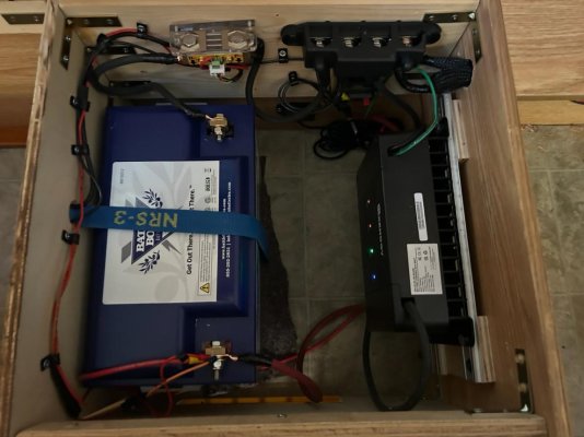
I installed an 80 amp Blue Sea CB at each end of the 6awg cable, close to the starting battery and just before the Renogy dcdc. I also installed a 30 amp CB on the +ve line between the camper battery and the distribution panel. The Renogy came with a 60 amp fuse and the manual shows this fuse between the camper battery and the dcdc. I didn’t do this thinking that the circuit breakers I installed on the 6awg line was adequate. Is this assumption correct?

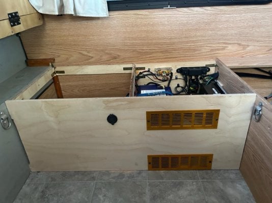
Here’s a few photos of the setup. Note the venting on the battery box for venting the box for the dcdc related heat. The intention is the upper and lower vents will establish a convection loop.

Any suggestions are always appreciated.
 
Photos…
 

Attachments

  • IMG_0765.jpeg
    IMG_0765.jpeg
    121.5 KB · Views: 44
  • IMG_0766.jpeg
    IMG_0766.jpeg
    95.5 KB · Views: 38
Thanks Vic for all your efforts on this site.

What follows is a list of the best practices I’ve learned about installing a dcdc. I hope any errors will be noted and omissions added.

  1. Choose the correct size wire to connect the truck battery to the camper dcdc. I chose 6 awg installing it in an F250 with a crew cab and a 6’9” bed. 4 awg would have served the purpose with lower voltage decrease. I used 6 awg welding cable for the connection. It was very easy to work with and probably worth the additional cost.
  2. Install the appropriate amperage circuit breakers at both ends of the 6 awg cable. I used the Blue Sea 80 amp breaker that is frequently recommended on this forum.
  3. I used two cable glands to pass the 6awg cable through the truck bed. I enlarged the hole that ATC made when they ran their 10 awg cable to the camper. I installed a common cable gland in the hole to protect the cable from the bed metal. Next I installed a marine cable gland to the truck bed exterior.
  4. I used a hammer crimper to crimp the cable lugs to the cable. For a hammer I used a hand held sledge hammer. A $9 solution that worked well. One caveat… you want to crimp your cables before installing them. That adds a little complexity to sizing the length of the 6 awg cable. I suppose that a ratchet style crimper would let you crimp the lug and cable after you installed the cable to the exact length.
  5. I used 75 amp Anderson Power Pole connectors in the passenger side front wheel well to connect the camper wiring to the cable from the truck battery.
  6. I terminated the ve- 6 awg cable to the chassis ground as suggested earlier in this thread. K7MDL raised this issue. I tested the output of my alternator using various loads (headlights, air conditioning etc) but the output held steady under all loads at 14.7x. I assume this indicates it is a standard not a smart alternator.
  7. I connected the ve- cable in the camper to a negative bus bar. I also connected any ve- cables from downstream loads to the negative busbar.
  8. I installed a Renogy 500 amp shunt and monitor. I connected one side of the shunt to the negative bus bar and the other side of the shunt to the ve- terminal on the lithium battery. I used some leftover 6 awg wellding cable for these connections. The welding cable makes it easy to work in the tight space of a camper battery box.
  9. I connected the ve+ cables to the Blue Sea circuit breakers.
  10. The Renogy dcdc was very easy to connect the required cables. The simplicity of the Renogy is a selling point, but I believe it lacks features that other dcdc chargers mentioned on this website have.
  11. I installed a 30 amp Blue Sea breaker in the 10 awg cable that runs between the truck and the distribution panel in the camper. Any additional ve+ cables in the camper not connected to the distribution box have an appropriate in line fuse.
 
Job: Upgrade wiring from the vehicle battery to camper battery in Four Wheel Camper
Goal: Reduce the time needed to recharge the camper battery
Specifics in my case: 2017 Fleet Shell model, routing from truck battery to the camper at a BlueSea BatteryLink™ Automatic Charging Relay - 12V/24V DC 120A
Cost: Estimated to be about $225 in materials plus $40 for a new tool (who doesn’t need a new tool?)
14 Jan 2024
 
If you are doing all this - I recommend adding a DC to DC charger near the auxiliary battery in the camper instead of an ACR for two reasons.

First, the DC to DC charger will take the incoming voltage and bump it up a bit to the proper charging profile needed by which ever type of battery is installed in the camper.

Second, in my now 19 year old truck with a 120 amp alternator - the DC to DC charger limits the maximum current draw from the truck battery.

Also, I used the Marinco 70 amp trolling motor plug and receptacle in my install - it require the use of a fairly deep electrical box at the front of the truck's cargo bed. In 20/20 hindsight, an Anderson plug rated for the proper amperage would have been easier to install.

https://www.amazon.com/Automotive-Female-Connector-Assembly-Mounting/dp/B07ZX27CPZ/ref=sr_1_2?crid=2GTPWGCN8BBKL&keywords=anderson%2Breceptacle%2B50%2Bamp&qid=1705760450&sprefix=anderson%2Breceptacle%2B50%2Bamp%2Caps%2C105&sr=8-2&th=1
 
Thanks TacomaAustin.
Are you recommending removing the existing BlueSea ACR and replacing with a DC DC charger? This almost doubles the cost of the upgrade.
Two options that I'm considering, both Victron - one is isolated and one is non-isolated, I don't run sensitive electronics from the camper battery while driving so it looks like a non-isolated charger would be OK. Any thoughts on this?
Amazon.com: Victron Energy Orion-Tr Smart 12/12-Volt 30 amp 360-Watt DC-DC Charger Non-Isolated (Bluetooth) : Automotive
Amazon.com: Victron Energy Orion-Tr Smart 12/12-Volt 30 amp 360-Watt DC-DC Charger Isolated (Bluetooth) : Automotive

I like that Anderson protective cover but I'm still left with the issue of protecting the cables where they route through the hole in the sidebed.

I'm not sure if it matters but I'm also upgrading to a SOK 208Ah lithium battery with a Victron MPPT controller (Victron Energy SmartSolar MPPT 100V 30 amp 12/24-Volt Solar Charge Controller (Bluetooth)) that will replace the existing Zamp PWM controller.
 
"I'm not sure if it matters but I'm also upgrading to a SOK 208Ah lithium battery with a Victron MPPT controller (Victron Energy SmartSolar MPPT 100V 30 amp 12/24-Volt Solar Charge Controller (Bluetooth)) that will replace the existing Zamp PWM controller"

If you plan on installing a 208Ah lithium battery, then I highly recommend installing a DC to DC charger to cap the amount of amps that can be drawn through your AWG #6 gauge wiring and boost the voltage up to the correct profile for a LiFePO4.

With regards to the Marinco plug and socket I have no quibbles over its build and performance other than to me it is bulky set up.
 
GaryRpg said:
Thanks TacomaAustin.
Are you recommending removing the existing BlueSea ACR and replacing with a DC DC charger? This almost doubles the cost of the upgrade.
Two options that I'm considering, both Victron - one is isolated and one is non-isolated, I don't run sensitive electronics from the camper battery while driving so it looks like a non-isolated charger would be OK. Any thoughts on this?
Amazon.com: Victron Energy Orion-Tr Smart 12/12-Volt 30 amp 360-Watt DC-DC Charger Non-Isolated (Bluetooth) : Automotive
Amazon.com: Victron Energy Orion-Tr Smart 12/12-Volt 30 amp 360-Watt DC-DC Charger Isolated (Bluetooth) : Automotive

I like that Anderson protective cover but I'm still left with the issue of protecting the cables where they route through the hole in the sidebed.

I'm not sure if it matters but I'm also upgrading to a SOK 208Ah lithium battery with a Victron MPPT controller (Victron Energy SmartSolar MPPT 100V 30 amp 12/24-Volt Solar Charge Controller (Bluetooth)) that will replace the existing Zamp PWM controller.
non-isolated is good enough. The isolated ones are designed for marine applications.... nothing like having a BIG voltage difference between the dock and the boat and thus between ones legs.... :oops:

I used to use a plastic grommet in a 3/4" hole to protect the wires. Now I use firewall pass through connectors from Summit Racing - Summit Racing SUM-G1431-RED Summit Racing™ Bulkhead Cable Connectors | Summit Racing

Yes, TacomaAustin is recommending that your ditch the ACR and go DCDC. I think you might find that without the DCDC, your 200+ AH LiFePo4 batteries will suck down more than 50A and trip your breakers. I'm using 2AWG wire and 100A breakers, because I also occasionally want to direct connect (I have a switch for that) both sets of batteries, like when I am boosting the truck from the camper, and/or trickle charging the truck from the camper.

As for the MPPT... Thanks for listing that item. I was confused about the 12/24 part of your description and had to look it up. I'm using the same MPPT and had no idea it was self selecting the battery voltage. Cool.

Also, when running your wires, are you running a pair, or just the one and using the frame as the ground return? I strongly recommend not using the frame.
 
DETAILED INTRUCTIONS FOR UPGRADING CHARGING CABLE FROM TRUCK TO CAMPER
Hi all,
I just upgraded my truck to camper wiring on my 2017 Fleet. It sounded simple at the beginning of the job, but I hit several snags along the way. So I wrote up a fairly detailed set of instructions with cost, materials, tools, methods and work process. It may look like way more than you might need, until you need it.

Bottom line:
Cost is about $200 for wires, fuses, etc. Add another $215 for a new DC to DC charger (which I needed for my new lithium battery). I bout another $75 in electrical tools - crimpers and wire strippers.
If you have everything collected, count on a day of time to do all the work.

Thanks to all who gave me advice as I worked out the details of this project.

Happy rewiring!

-Gary
 
GaryRpg said:
DETAILED INTRUCTIONS FOR UPGRADING CHARGING CABLE FROM TRUCK TO CAMPER
Hi all,
I just upgraded my truck to camper wiring on my 2017 Fleet. It sounded simple at the beginning of the job, but I hit several snags along the way. So I wrote up a fairly detailed set of instructions with cost, materials, tools, methods and work process. It may look like way more than you might need, until you need it.

Bottom line:
Cost is about $200 for wires, fuses, etc. Add another $215 for a new DC to DC charger (which I needed for my new lithium battery). I bout another $75 in electrical tools - crimpers and wire strippers.
If you have everything collected, count on a day of time to do all the work.

Thanks to all who gave me advice as I worked out the details of this project.

Happy rewiring!

-Gary
Gary, have you got that write up available to share?
 
K7MDL said:
The F-150 uses a hall effect current sensor the negative battery lead for the internal battery monitoring system (BMS) which in turn controls the alternator output among other things. Connecting to the battery neg post would bypass that sensor and not let it see the actual state of the battery current draw thus altering the calculated battery SOC. The F-250 may also have a BMS from what I can see. I would use the chassis connection. They will both work though.
For what its worth the factory wiring for the winch option on the superduty is wired to the battery terminal, but they may be assuming minimal usage in that decision vs something like a DC-DC charger regularly drawing power?
 
pods8 said:
For what its worth the factory wiring for the winch option on the superduty is wired to the battery terminal, but they may be assuming minimal usage in that decision vs something like a DC-DC charger regularly drawing power?
This may be due to the size of the stock battery to chassis ground wire jumper. The winch probably can draw far higher currents so they are bypassing this jumper rather than upgrade the jumper. I do not have a F-250 so do not know what size they use. Just a guess. At winch currents, the battery voltage will draw down and cause the necessary reactions regardless.

In my 2016 F-150 I have a long-standing parasitic drain problem I have yet to troubleshoot. My battery will be dead in 2 weeks of sitting, sometimes less. The BMS tries to shut stuff off but not enough. Keeping my camper on the truck lets the solar keep the battery topped off letting me procrastinate longer :).
 
Came across this today. Gives some insight to the BMS and hall effect sensor used in the battery negative lead.
G0000144 12 Volt Battery Charging and Testing Quick Reference Guide.pdf

There are 2 types of sensors defined in this doc, one for Auto Start-Stop and the other without.
 
K7MDL said:
This may be due to the size of the stock battery to chassis ground wire jumper. The winch probably can draw far higher currents so they are bypassing this jumper rather than upgrade the jumper. I do not have a F-250 so do not know what size they use. Just a guess. At winch currents, the battery voltage will draw down and cause the necessary reactions regardless.
Yeah the stall current is up near 400amps. Not sure the battery to chassis gauge offhand but the winch is 2ga I believe.
 
Back
Top Bottom