A.Smith
Advanced Member
I am wiring a Dc to Dc Charger and Solar Panel and controller
into my 2006 Hawk.
# 4 welding cable from the truck battery to a 100A 285 series circuit breaker ( next to the battery) to 100A circuit breaker in the camper area ( next to the battery /component area) , The wiring will be split at the circuit breaker, because #4 will not feed into the charger without an extreme loss of wires, therefore #6 wire. If this is not advised,suggestions, a buss bar ?
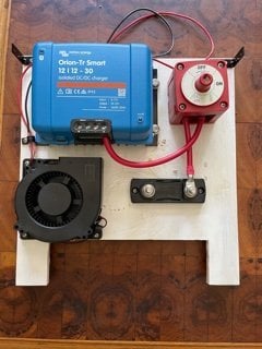
#6 wire out of the series 285 circuit breaker to the Victron DC to DC Smart Charger 12/12-30m to
? fuse to the 100A BB Lithium Battery.
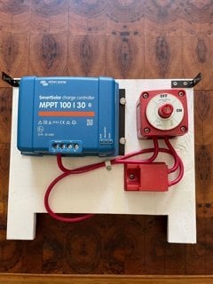
Solar; 100 watt Renogy pane. Victron MPPT 100/30 charge controller.
#8 wire from the solar panel to the controller to
? fuse, to the Lithium battery.
A Victron BMV 712 battery monitor will be wired into the system.
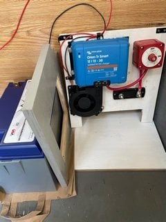
As the component area is small, service loops will be installed behind each component panel for maintenance.
So as you can see I need Help.
Thanks
Fred
A.Smith
Pictures did not show, will try again.
+ In writing this piece I had many re-do's as trying to load pictures caused everything to cancel so I had to start again, and again.
As the pictures show I can mechanically complete connections, but I admit I am weak on theory. I have been posting questions and reading everything I could find on this forum. The wiring fuse charts from Blue Sea Systems have confused me therefore this recent asking for help.
Some aspects are redundant, like the switches. I am overly cautious until I thoroughly understand. And this project is a bit overwhelming at times.
One or more of the previous owners had electrical fires unbeknownst to me. therefore I have had to tear apart the interior far more than planed. But by pulling the water holding tank and numerous charred boards and wiring, I have created a larger batter/component area.
Thanks to all for this and previous help.
into my 2006 Hawk.
# 4 welding cable from the truck battery to a 100A 285 series circuit breaker ( next to the battery) to 100A circuit breaker in the camper area ( next to the battery /component area) , The wiring will be split at the circuit breaker, because #4 will not feed into the charger without an extreme loss of wires, therefore #6 wire. If this is not advised,suggestions, a buss bar ?
#6 wire out of the series 285 circuit breaker to the Victron DC to DC Smart Charger 12/12-30m to
? fuse to the 100A BB Lithium Battery.
Solar; 100 watt Renogy pane. Victron MPPT 100/30 charge controller.
#8 wire from the solar panel to the controller to
? fuse, to the Lithium battery.
A Victron BMV 712 battery monitor will be wired into the system.
As the component area is small, service loops will be installed behind each component panel for maintenance.
So as you can see I need Help.
Thanks
Fred
A.Smith
Pictures did not show, will try again.
+ In writing this piece I had many re-do's as trying to load pictures caused everything to cancel so I had to start again, and again.
As the pictures show I can mechanically complete connections, but I admit I am weak on theory. I have been posting questions and reading everything I could find on this forum. The wiring fuse charts from Blue Sea Systems have confused me therefore this recent asking for help.
Some aspects are redundant, like the switches. I am overly cautious until I thoroughly understand. And this project is a bit overwhelming at times.
One or more of the previous owners had electrical fires unbeknownst to me. therefore I have had to tear apart the interior far more than planed. But by pulling the water holding tank and numerous charred boards and wiring, I have created a larger batter/component area.
Thanks to all for this and previous help.