portermoab
Member
Hi All- after a few hours of confusion trying to install a solar controller in my 2018 Raven, I think I found the issue, although I want to check before I cut the positive and negative wires.
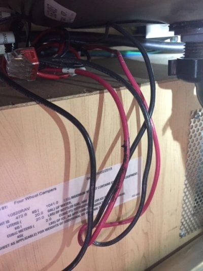
It appears that FWC did not cut the positive and negative wires for the solar controller after the wago connection. As I believe it should go, there should be a two positive and two negative wires coming into the wago connection (coming from the roof and rear solar plugs). One positive and one negative wire should leave the wago connection from the middle terminal (this wire is labeled battery/solar connection). Shortly after leaving the wago connection the positive and negative wires should be cut so that it can be wired into the PV input on the solar charger (essentially where they bend in the photo below). Then, the other side of these wires should be wired into the battery output on the solar charger, which then continues to the battery compartment. Does this make sense? Currently it's just one continuous wire from the wago connection to the battery compartment, which makes me think FWC just didn't cut the wires.
Here's a photo if it helps.
Thanks for any input...just wanting to double check before cutting the positive and negative battery/solar connection wire after the wago connection.
Neal