This post is intended to describe the recent installation of a 100w solar panel on a Yakima rack and a PWM charge controller in a FWC Fleet that is about a year old now. Since many posts on WtW were extremely helpful for this project, I thought conveying my experiences might be useful for anyone thinking about taking on a similar installation. I was really nervous about doing this project but it turned out to be much easier (for the most part) than I expected. The last section will be about what I might do differently if I were to do it again. Apologies too for the length of this post but i thought some of you might be interested in some of the details
.
A few important ‘Thank You’s’ to start. First, thanks to Leadsled9 for his detailed posts from 2010 about installing a panel on Yakima racks. Installing the panel on a Yakima system was my preference as I did not want to drill additional holes in the roof and had the rack already for carrying skis. It is not likely that I would have taken this project on by myself without the guidance in those posts. Mandatory reading for anyone thinking about installing on Yakima racks. Thanks also to Doug and Roger from AM Solar in Springfield Oregon for their advice on the components and the install. Thanks lastly to HandyBob for the information on his site – his articles can be tough to read but contain a ton of useful information.
About the components: we selected the GS100 panel from AM Solar. This is a 100w panel from Grape Solar. While it is a little more spendy than other 100w panels, it weighs in at about 14.5lbs which was, by far, the lightest weight panel we found for the wattage. Based on the recommendation from AM Solar, we went with the Sun Charger 30 (SC30) PWM charge controller from Blue Sky Energy. The decision was between the SC30 and the Morningstar Sunsaver 20l PWM. We chose the Blue Sky unit it because it has a digital readout of various data points and is programmable. A few comments about this choice will come later. We seriously considered an MPPT charge controller but were advised that it was not worth the extra money for a small system like ours. This was a tough decision because you want the system to perform as efficiently as possible but in the end decided to go with the PWM recommendation. There are definite pros and cons for both technologies that are widely debated on this and other forums so it is definitely worth some research to understand the differences and benefits.
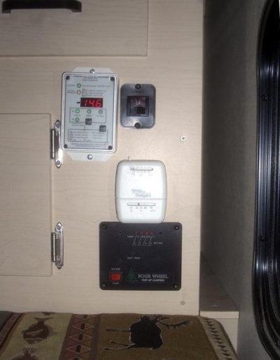
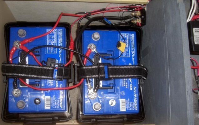
Out Fleet has the FWC standard two AGM auxiliary battery configuration. We started with the charge controller since it was a wet weekend in Oregon. Our unit is configured with the side dinette so there is a small cabinet just above the battery compartment which is where we decided to install the controller (picture below). I thought the biggest problem would be making the cutout in the side of the cabinet because there is not much room for power tools in that part of the camper. I used a Ryobi plunge cutter and it worked really well. Running the wires was the difficult part. AM Solar recommended 8 gauge wire but that gauge wire turned out to be too difficult to use because there was not enough room to make a downward 90 degree turn to the battery compartment plus the tightening screws on the controller had a cross pattern so neither a Philips head or slot screw driver head worked well enough to tighten the 8 gauge wire. So, after a trip to Home Depot for some 10 gauge wire and a new tool, I was able to complete the battery connections. The hole in the bottom of the cabinet where the wires come out did not turn out very well because there is a metal screw or rod or something else right in the middle of it. Fortunately, the seat cushion is taller than the hole so you really do not see it or the wires.
The installation of the panel was uneventful. I had ordered the L shaped brackets that Leadsled9 used to support his panel from the bottom but the GS100 did not have flanges on the bottom on the panel ends, probably as a result of trying to save weight. Dave from AM Solar told me that I could drill a hole in the side wall of the panel so that is what we did and then attached the panel to the rack cross bars with a bolt and washers just like it was a typical Yakima attachment (picture below). If you are wondering why there is only 1 Yakima lock on the crossbar in the picture, it is because those things cost $17 apiece and it seemed like having just one lock on the front bar and one on the back would be a big enough theft deterrent . I am not crazy about how it looks though so may end up springing for two more locks.
As for performance, we have not had a chance to field test the setup yet. But we have been observing the panel output via the display on the charge controller and it seems to deliver decent amperage even on very cloudy, rainy days. We are very happy that we no longer need to plug the camper into auxiliary power every few weeks to top off the batteries.
So what would we do if we did this again? I am not sure I would choose the same charge controller. The battery compartment in the Fleet has a perfect location for the Morningstar controller, probably because that is what FWC provides with the solar option. HandyBob is a huge proponent of those controllers and I am not sure the geek factor of the Blue Sky product is worth the trouble of installing it. It is nice to see the data in the various displays but it does not tell us anything we could not get from the Trimetric 2025RV monitor that was installed last summer. It is likely that the appreciation of the data display will grow as the memory of the install fades but I wanted to point out that installing the Morningstar is much simpler and should be considered.
So that is our solar install story. The net of it is that we are happy with the way it turned out and are confident that the investment will be a real asset to our travels. Feel free to PM me with any questions. Thanks for reading!
-steelhead


.
A few important ‘Thank You’s’ to start. First, thanks to Leadsled9 for his detailed posts from 2010 about installing a panel on Yakima racks. Installing the panel on a Yakima system was my preference as I did not want to drill additional holes in the roof and had the rack already for carrying skis. It is not likely that I would have taken this project on by myself without the guidance in those posts. Mandatory reading for anyone thinking about installing on Yakima racks. Thanks also to Doug and Roger from AM Solar in Springfield Oregon for their advice on the components and the install. Thanks lastly to HandyBob for the information on his site – his articles can be tough to read but contain a ton of useful information.
About the components: we selected the GS100 panel from AM Solar. This is a 100w panel from Grape Solar. While it is a little more spendy than other 100w panels, it weighs in at about 14.5lbs which was, by far, the lightest weight panel we found for the wattage. Based on the recommendation from AM Solar, we went with the Sun Charger 30 (SC30) PWM charge controller from Blue Sky Energy. The decision was between the SC30 and the Morningstar Sunsaver 20l PWM. We chose the Blue Sky unit it because it has a digital readout of various data points and is programmable. A few comments about this choice will come later. We seriously considered an MPPT charge controller but were advised that it was not worth the extra money for a small system like ours. This was a tough decision because you want the system to perform as efficiently as possible but in the end decided to go with the PWM recommendation. There are definite pros and cons for both technologies that are widely debated on this and other forums so it is definitely worth some research to understand the differences and benefits.
Out Fleet has the FWC standard two AGM auxiliary battery configuration. We started with the charge controller since it was a wet weekend in Oregon. Our unit is configured with the side dinette so there is a small cabinet just above the battery compartment which is where we decided to install the controller (picture below). I thought the biggest problem would be making the cutout in the side of the cabinet because there is not much room for power tools in that part of the camper. I used a Ryobi plunge cutter and it worked really well. Running the wires was the difficult part. AM Solar recommended 8 gauge wire but that gauge wire turned out to be too difficult to use because there was not enough room to make a downward 90 degree turn to the battery compartment plus the tightening screws on the controller had a cross pattern so neither a Philips head or slot screw driver head worked well enough to tighten the 8 gauge wire. So, after a trip to Home Depot for some 10 gauge wire and a new tool, I was able to complete the battery connections. The hole in the bottom of the cabinet where the wires come out did not turn out very well because there is a metal screw or rod or something else right in the middle of it. Fortunately, the seat cushion is taller than the hole so you really do not see it or the wires.
The installation of the panel was uneventful. I had ordered the L shaped brackets that Leadsled9 used to support his panel from the bottom but the GS100 did not have flanges on the bottom on the panel ends, probably as a result of trying to save weight. Dave from AM Solar told me that I could drill a hole in the side wall of the panel so that is what we did and then attached the panel to the rack cross bars with a bolt and washers just like it was a typical Yakima attachment (picture below). If you are wondering why there is only 1 Yakima lock on the crossbar in the picture, it is because those things cost $17 apiece and it seemed like having just one lock on the front bar and one on the back would be a big enough theft deterrent . I am not crazy about how it looks though so may end up springing for two more locks.
As for performance, we have not had a chance to field test the setup yet. But we have been observing the panel output via the display on the charge controller and it seems to deliver decent amperage even on very cloudy, rainy days. We are very happy that we no longer need to plug the camper into auxiliary power every few weeks to top off the batteries.
So what would we do if we did this again? I am not sure I would choose the same charge controller. The battery compartment in the Fleet has a perfect location for the Morningstar controller, probably because that is what FWC provides with the solar option. HandyBob is a huge proponent of those controllers and I am not sure the geek factor of the Blue Sky product is worth the trouble of installing it. It is nice to see the data in the various displays but it does not tell us anything we could not get from the Trimetric 2025RV monitor that was installed last summer. It is likely that the appreciation of the data display will grow as the memory of the install fades but I wanted to point out that installing the Morningstar is much simpler and should be considered.
So that is our solar install story. The net of it is that we are happy with the way it turned out and are confident that the investment will be a real asset to our travels. Feel free to PM me with any questions. Thanks for reading!
-steelhead
")