ntsqd
Custom User Title
When I spotted that the OE spare tire carrier winch's cable on our '96 CTD was starting to fray I knew that I needed to do something different and soon as we were heading to Toroweep in less than 2 months. The 315/75R16 spare didn't fit well under the truck and while conveniently out of the way I've never cared for having the spare where it potentially could be inaccessible.
The first consideration is that a spare of this size is not light. It quite possibly weighs more than my wife, so how was she going to be able to handle it if I were incapacitated and she had to change a flat? I didn't particularly relish the idea of lifting it myself, so a self-lifting design of some sort was indicated.
The next consideration was that while most rock-crawler types tend to use a pivot assembly based on a small trailer spindle, those do tend to fail from fatigue due to being a cantilevered, "single shear" type of design. I wanted double shear on all hinge pins. The second problem with the trailer spindle concept is that they swing too easily, not uncommon for the wind to blow them fully open or fully shut when unlatched, or for gravity to insist on swinging it to were it's most in the way. Easy to open and close, but not too easy and with a latch of some sort at the fully open position were goals. I elected to use flanged oilite-bronze bushings from McMaster-Carr on 1-1/8" OD tube or bar stock. (It turns out that round tube stock isn't all that round and was a headache to make work right, so I won't be doing exactly that again.)
Next was the latch's details. I have seen a lot of swing-a-way designs where it was clear to me that the designer was either clueless about how to best employ a latch or they missed a perfect opportunity to add additional support to the swinging assembly. I wanted the latch to not only hold the swinger closed, but also to add some additional support to the swinger so that the hinge assembly wasn't carrying all of the eccentric load.
And last was what to mount it to. With a sheet metal bed and an OE rear bumper I knew that it needed to be on one or the other, but not both. Sheet metal always makes me nervous. It can take fantastic loads, but those need to be applied and distributed correctly or it will fail. In looking over the bed I realized that my best bet was to use the stock tailgate mounting locations as they would be the best suited to distributing localized loads. I wasn't and still am not convinced that they're up to this sort of loading, but I feel that there aren't any better options short of building a flatbed for the truck and including the necessary mounts for the swing-away (a distinct future possibility).
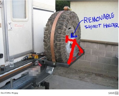
What I came up with: (not quite finished in these pics)

I used a Harbor Fright strap type boat tongue winch for lifting and lowering duties. This was a find as I had not been happy with any of the concepts that I'd come up with. They were all too complex and lacking in enough leverage. Even after having to cut down the length of the handle slightly my wife can easily crank the assembly up into place. the ratchet strap that holds the spare in place is long enough that it can be unwound and laid on the ground under the spare. Flipping it into place allows the user to ratchet the spare up off the ground and into the carrier.

Detail view of the latch. Those are black Delrin scuff/wear plates screwed to the latch jaw. The De-Sta-Co latch is angled to draw the jaw forward and down onto the corner of the main tube.

Detail view of the latch in the closed position. There has since been a load distributing plate added that spans across the open ended tube and caps it off.

Detail view of how the main mount tube assembly attaches to the latch post for the tailgate. I considered removing the post and just picking up the captured nut, but decided that I'd want the post there if I ever need to use the tailgate again. The rusty parts are a pair of weldable two piece shaft collars form McMaster-Carr. The bolt heads visible on the far side of the 2" tube are thru-bolted into the circular features (gray) above and below the shaft collars. That are also two blind threaded bolts not seen on the forward side of the 2" tube.

The first consideration is that a spare of this size is not light. It quite possibly weighs more than my wife, so how was she going to be able to handle it if I were incapacitated and she had to change a flat? I didn't particularly relish the idea of lifting it myself, so a self-lifting design of some sort was indicated.
The next consideration was that while most rock-crawler types tend to use a pivot assembly based on a small trailer spindle, those do tend to fail from fatigue due to being a cantilevered, "single shear" type of design. I wanted double shear on all hinge pins. The second problem with the trailer spindle concept is that they swing too easily, not uncommon for the wind to blow them fully open or fully shut when unlatched, or for gravity to insist on swinging it to were it's most in the way. Easy to open and close, but not too easy and with a latch of some sort at the fully open position were goals. I elected to use flanged oilite-bronze bushings from McMaster-Carr on 1-1/8" OD tube or bar stock. (It turns out that round tube stock isn't all that round and was a headache to make work right, so I won't be doing exactly that again.)
Next was the latch's details. I have seen a lot of swing-a-way designs where it was clear to me that the designer was either clueless about how to best employ a latch or they missed a perfect opportunity to add additional support to the swinging assembly. I wanted the latch to not only hold the swinger closed, but also to add some additional support to the swinger so that the hinge assembly wasn't carrying all of the eccentric load.
And last was what to mount it to. With a sheet metal bed and an OE rear bumper I knew that it needed to be on one or the other, but not both. Sheet metal always makes me nervous. It can take fantastic loads, but those need to be applied and distributed correctly or it will fail. In looking over the bed I realized that my best bet was to use the stock tailgate mounting locations as they would be the best suited to distributing localized loads. I wasn't and still am not convinced that they're up to this sort of loading, but I feel that there aren't any better options short of building a flatbed for the truck and including the necessary mounts for the swing-away (a distinct future possibility).
What I came up with: (not quite finished in these pics)
I used a Harbor Fright strap type boat tongue winch for lifting and lowering duties. This was a find as I had not been happy with any of the concepts that I'd come up with. They were all too complex and lacking in enough leverage. Even after having to cut down the length of the handle slightly my wife can easily crank the assembly up into place. the ratchet strap that holds the spare in place is long enough that it can be unwound and laid on the ground under the spare. Flipping it into place allows the user to ratchet the spare up off the ground and into the carrier.
Detail view of the latch. Those are black Delrin scuff/wear plates screwed to the latch jaw. The De-Sta-Co latch is angled to draw the jaw forward and down onto the corner of the main tube.
Detail view of the latch in the closed position. There has since been a load distributing plate added that spans across the open ended tube and caps it off.
Detail view of how the main mount tube assembly attaches to the latch post for the tailgate. I considered removing the post and just picking up the captured nut, but decided that I'd want the post there if I ever need to use the tailgate again. The rusty parts are a pair of weldable two piece shaft collars form McMaster-Carr. The bolt heads visible on the far side of the 2" tube are thru-bolted into the circular features (gray) above and below the shaft collars. That are also two blind threaded bolts not seen on the forward side of the 2" tube.