Jack
Senior Member
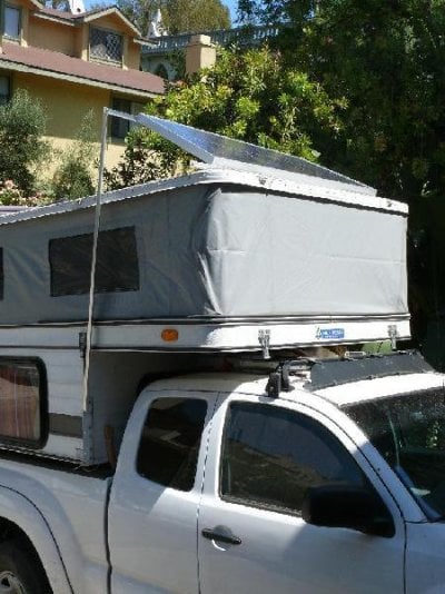
After a good bit of research (see http://www.wanderthewest.com/forum/showthread.php?t=1332) and two weekends, the PV panel is now mounted and running.
We got a 120W Mitsubishi panel and a MorningStar SS-10L-12 charge controller from Alter Systems. There are other good vendors out there, but what is important is that you get a reasonably efficient PV panel (12% or better) and an MPPT (Maximum Power Point Tracking) charge controller. The MPPT type charge controller optimizes your power under less than optimal conditions (ie, when it's not high noon in SoCal). It's well worth the extra bucks, since it can increase the power out of the PV panel by 25% at lower light levels. You don't need an "RV kit", just the PV panel and the charge controller. Check with the vendor to make sure the charge controller is appropriate for the PV panel (current rating, etc.)
You pick your PV panel wattage based on usage. Take the current output of the PV panel (6.7A for our 120W PV panel) and multiply by 8. You get more in the summer and less in the winter, but this is a good working number for 3/4 of the year. Now, for FWC, figure 4 amps each for the roof fan and heater fans. If you use LEDs for lighting (see http://www.wanderthewest.com/forum/showthread.php?t=1070) they hardly count (.3A). For incandescent, 1.5A per bulb or 6A if all interior lights are on. For us, we add two laptops at 5A each. Now multiply the current for each device times the hours you expect to use it in one day in summer and one day in winter and take the larger of the two results. This came to about 58 amps/day for us. Our PV panel, at 6.7A for 8 hours, comes to 53 amps/day. (Ok, we also have a 1KW Yamaha generator (similar specs to the 1KW Honda but cheaper) so if we mis-calculated or for winter time in the Pacific Northwest coast.)
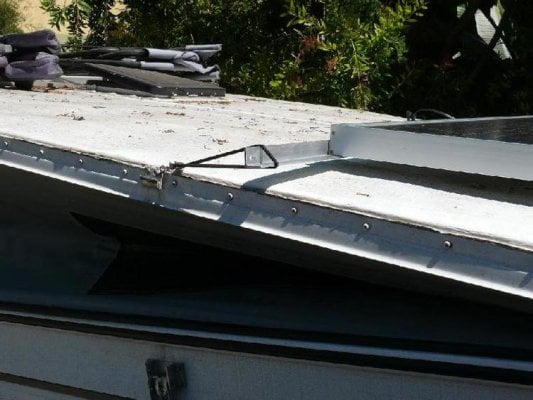
We mounted the panel to the front bar of the FWC roof rack with two 1 foot stainless steel piano hinges. If you already have the PV Panel connector on the roof (I think FWC does this standard, now) you need a molded two-connector automotive plug (see http://www.delcity.net/delcity/servlet/catalog?parentid=8771&childid=84009&page=1&tabset=1&pageitem=1&new=y for picture). Make sure that the exposed connector is the negative output from the PV so that when you unplug it, it won't short to the chassis. This should also be the black wire, which, on the Eagle, is under the wooden cover between the front of the camper and the front of the kitchen unit on the drivers side. But buzz the wires it out just to make sure!
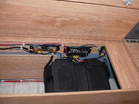
Connect the PV panel to the charge controller and the battery to the charge controller. It is best to place the charge controller near the battery so that the voltage drop from the charge controller to the battery is minimized. Also, place a fuse on the positive side for both the battery connection and the PV panel connection. This is to protect both the charge controller and the PV panel. Since it was a 10A charge controller, we chose 10A fuses. The charge controller basically takes the output of the PV panel, which can range from 20V to 12V and 6.7A to a lot less and optimizes it to 12.6V (or so) and whatever current is being produced. We did not connect any load to the charge controller because the electric distribution panel is on the other side of the camper and the wiring would have gotten quite complicated with the converter and alternator connections. The advantage of connecting the load is that the charge controller will disconnect the battery (which means the "loads" will be turned off) when the battery is too low, thus protecting the battery from being over discharged (and potentially killed). If you install an inverter (12V DC to 115V AC), you may want to connect it to the load connections on the charge controller.
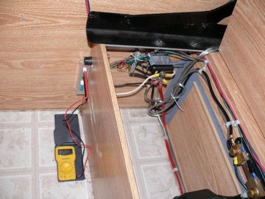
Having killed one battery by discharging it completely, I intended in the future to install a battery cut-off switch. Also, we used 10 gauge instead of 12 gauge braided wire (and braided wire is so much easier to route than single strand) to minimize voltage drop.
An aside about voltage drop for the non electricians and engineers. The goal is to get as much power to the consumer devices in the system as possible. Wire size is like a hose diameter and current is like the water. The narrower the hose, the more energy (voltage) it takes to push the same amount of water (current) through the hose. That means that the narrower the hose, the less energy there is at the device. In electrical terms, the resistance of the wire is part of the load and the wire and the load act as a three resistance voltage divider. Since current stays the same and since the power at the device is current x voltage, the higher the voltage at the device the more power. The $1 or so difference in wire cost buys about 1 watt of PV panel power. The difference between a 120W PV panel and a 123 PV panel is about $40.
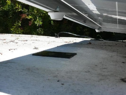
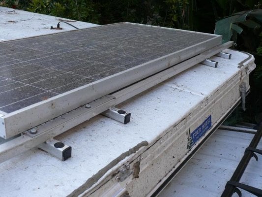
To support the PV panel, we glued rubber pads (adhesive cement) to the roof and attached rubber feet to the PV panel. The hope is that either can be replaced as they wear, without ever damaging the roof or the panel.
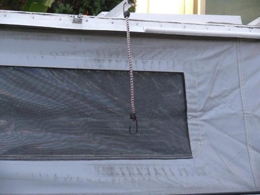
Tying down the panel during travel is not a final solution. The bungee cord is a bit minimal. I'm looking for rubber loops with twin hooks, but other suggestions are most welcome. The loop attached to the roof latch are just figure eight loops, with one end under the screw.
I also put shunts on the negative side of the battery and the PV panel (0.1 Ohm) and attached sense lines from them and the positive side of the battery and PV panel to test probe connectors. A $10 Radio Shack DMM lets me see the voltages and currents for both the battery and the PV panel - far cheaper (and a bit less battery draw) than the optional readouts for the charge controller and the battery (OK, the shunts were free, otherwise, buy the readout LCDs).
We got a 120W Mitsubishi panel and a MorningStar SS-10L-12 charge controller from Alter Systems. There are other good vendors out there, but what is important is that you get a reasonably efficient PV panel (12% or better) and an MPPT (Maximum Power Point Tracking) charge controller. The MPPT type charge controller optimizes your power under less than optimal conditions (ie, when it's not high noon in SoCal). It's well worth the extra bucks, since it can increase the power out of the PV panel by 25% at lower light levels. You don't need an "RV kit", just the PV panel and the charge controller. Check with the vendor to make sure the charge controller is appropriate for the PV panel (current rating, etc.)
You pick your PV panel wattage based on usage. Take the current output of the PV panel (6.7A for our 120W PV panel) and multiply by 8. You get more in the summer and less in the winter, but this is a good working number for 3/4 of the year. Now, for FWC, figure 4 amps each for the roof fan and heater fans. If you use LEDs for lighting (see http://www.wanderthewest.com/forum/showthread.php?t=1070) they hardly count (.3A). For incandescent, 1.5A per bulb or 6A if all interior lights are on. For us, we add two laptops at 5A each. Now multiply the current for each device times the hours you expect to use it in one day in summer and one day in winter and take the larger of the two results. This came to about 58 amps/day for us. Our PV panel, at 6.7A for 8 hours, comes to 53 amps/day. (Ok, we also have a 1KW Yamaha generator (similar specs to the 1KW Honda but cheaper) so if we mis-calculated or for winter time in the Pacific Northwest coast.)
We mounted the panel to the front bar of the FWC roof rack with two 1 foot stainless steel piano hinges. If you already have the PV Panel connector on the roof (I think FWC does this standard, now) you need a molded two-connector automotive plug (see http://www.delcity.net/delcity/servlet/catalog?parentid=8771&childid=84009&page=1&tabset=1&pageitem=1&new=y for picture). Make sure that the exposed connector is the negative output from the PV so that when you unplug it, it won't short to the chassis. This should also be the black wire, which, on the Eagle, is under the wooden cover between the front of the camper and the front of the kitchen unit on the drivers side. But buzz the wires it out just to make sure!
Connect the PV panel to the charge controller and the battery to the charge controller. It is best to place the charge controller near the battery so that the voltage drop from the charge controller to the battery is minimized. Also, place a fuse on the positive side for both the battery connection and the PV panel connection. This is to protect both the charge controller and the PV panel. Since it was a 10A charge controller, we chose 10A fuses. The charge controller basically takes the output of the PV panel, which can range from 20V to 12V and 6.7A to a lot less and optimizes it to 12.6V (or so) and whatever current is being produced. We did not connect any load to the charge controller because the electric distribution panel is on the other side of the camper and the wiring would have gotten quite complicated with the converter and alternator connections. The advantage of connecting the load is that the charge controller will disconnect the battery (which means the "loads" will be turned off) when the battery is too low, thus protecting the battery from being over discharged (and potentially killed). If you install an inverter (12V DC to 115V AC), you may want to connect it to the load connections on the charge controller.
Having killed one battery by discharging it completely, I intended in the future to install a battery cut-off switch. Also, we used 10 gauge instead of 12 gauge braided wire (and braided wire is so much easier to route than single strand) to minimize voltage drop.
An aside about voltage drop for the non electricians and engineers. The goal is to get as much power to the consumer devices in the system as possible. Wire size is like a hose diameter and current is like the water. The narrower the hose, the more energy (voltage) it takes to push the same amount of water (current) through the hose. That means that the narrower the hose, the less energy there is at the device. In electrical terms, the resistance of the wire is part of the load and the wire and the load act as a three resistance voltage divider. Since current stays the same and since the power at the device is current x voltage, the higher the voltage at the device the more power. The $1 or so difference in wire cost buys about 1 watt of PV panel power. The difference between a 120W PV panel and a 123 PV panel is about $40.
To support the PV panel, we glued rubber pads (adhesive cement) to the roof and attached rubber feet to the PV panel. The hope is that either can be replaced as they wear, without ever damaging the roof or the panel.
Tying down the panel during travel is not a final solution. The bungee cord is a bit minimal. I'm looking for rubber loops with twin hooks, but other suggestions are most welcome. The loop attached to the roof latch are just figure eight loops, with one end under the screw.
I also put shunts on the negative side of the battery and the PV panel (0.1 Ohm) and attached sense lines from them and the positive side of the battery and PV panel to test probe connectors. A $10 Radio Shack DMM lets me see the voltages and currents for both the battery and the PV panel - far cheaper (and a bit less battery draw) than the optional readouts for the charge controller and the battery (OK, the shunts were free, otherwise, buy the readout LCDs).