Mounting Victron 100/20a Solar Charge Controller in Fleet Shell

buffcrkrunner

New Member
Joined
Feb 4, 2020
Messages
4
Hi,
I am new to this forum. I just purchased a FWC Fleet Shell last week and am looking to install a Victron SmartSolar 100v/20a charge controller. My Shell has the flush mount stove and furnace and two 12vdc batteries. I was thinking of installing the controller in the battery box next to the batteries on the rear wall since it is 1/2 inch plywood with the gray finish on it. The controller will just fit between the battery and the rear wall.

The spec sheet for the controller calls for it to be mounted on a "non-flammable substrate". That has me a little concerned about mounting on the inside of the battery box. The advantage to mounting there is that the wires coming from the outside connectors for solar panels end inside the battery box. Also the spec sheet mentions that the ambient temperature of the controller should be within 5 degrees C of the batteries.

I am planning to use a 200 watt panel so I guess I could use a 75v/15a controller. I was not planning to use the load control part of the solar controller.

Do any of you have experience with Victron solar charge controller and have any recommendations on installing one? Any pictures you could share?

Thanks.
 
I have two 120W commodity flex panels on the roof run in parallel. My two batteries are run in parallel. I would suggest the 100/20. It’s nice to be able to add, & have options, if need be. Yes, as Vic says below, more is better. My Grandby Shell cabinet was tight but doable.
 

Attachments

  • 4F80435E-14A6-4F16-A59F-A0CBF05E5ABD.jpeg
    4F80435E-14A6-4F16-A59F-A0CBF05E5ABD.jpeg
    274.5 KB · Views: 339
buffcrkrunner said:
Hi,
I am new to this forum. I just purchased a FWC Fleet Shell last week and am looking to install a Victron SmartSolar 100v/20a charge controller. My Shell has the flush mount stove and furnace and two 12vdc batteries. I was thinking of installing the controller in the battery box next to the batteries on the rear wall since it is 1/2 inch plywood with the gray finish on it. The controller will just fit between the battery and the rear wall.

The spec sheet for the controller calls for it to be mounted on a "non-flammable substrate". That has me a little concerned about mounting on the inside of the battery box. The advantage to mounting there is that the wires coming from the outside connectors for solar panels end inside the battery box. Also the spec sheet mentions that the ambient temperature of the controller should be within 5 degrees C of the batteries.

I am planning to use a 200 watt panel so I guess I could use a 75v/15a controller. I was not planning to use the load control part of the solar controller.

Do any of you have experience with Victron solar charge controller and have any recommendations on installing one? Any pictures you could share?

Thanks.
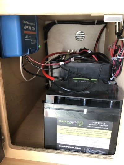
Do you have room to put about 1/2" of washers or some kind of metal tubing around the mounting screws? That's what I did. But honestly the unit does not usually run warm, never mind hot.

Go bigger rather than smaller, if you have the space and $$$. 75/15 is borderline with the 200w panel. 200w * .85% efficiency / 12V = 14.2A.

Check out my More Power Scotty thread... http://www.wanderthewest.com/forum/topic/13230-i-need-more-power-scotty/
 
Thanks Stokeme and Vic. Very useful information and eases my mind. I'll go with the 100/20 and see if I can put some spacers on the mounting screws.
 
I have the 100/30 and it never feels warm. Mine is mounted to a cabinet side panel with bolts and I spaced it away from the panel with a stack of washers.
 
I just upgraded my 2016 Fleet from a PWM controller to the Victron 100/20. I have two 75ah batteries and two 100W flexible panels and I may add a 100W portable to the mix, which the 100/20 will handle.

You might also consider adding a Victron battery monitor while you are installing the controller. As many on this forum have done, I installed the Victron BM-712. Wish I had done this 4 years ago!

I don't know what electrical appliances you currently have or are planning to add (e.g., additional lights, 2-way fridge, furnace, inverter, etc.) and how you plan to use your camper (i.e., mainly weekends vs. extended trips) and in what conditions (i.e., mainly summer vs. shoulder seasons or mainly sunny vs. shady, rainy, cloudy, snowy conditions). The ROI on the monitor be higher if you camp for extended periods and/or in more variable conditions. Having a good monitor will reduce the guess work and allow you to learn how to manage your batteries and electrical use, and also trouble shoot problems. It's a pretty easy install (once you figure it out) and as per above, you'll find lots of help on this forum. Enjoy your camper!
 
I have the Victron 100/20 in my Hawk. Using the output is nice to see what you are using. Victron also has a great Bluetooth app for your phone to monitor what is going on.
 
billharr said:
I have the Victron 100/20 in my Hawk. Using the output is nice to see what you are using. Victron also has a great Bluetooth app for your phone to monitor what is going on.
Bill, you have the Victron BMV too, right?
 
billharr said:
No I am just using the App. I do have a voltage meter that I put in when I did my build.
OK. So, there is an App for both the MPPT controller and the BMV. Just clarifying ... because it is the BMV that tells you your battery SOC, not the MPPT.
 
Vic Harder said:
OK. So, there is an App for both the MPPT controller and the BMV. Just clarifying ... because it is the BMV that tells you your battery SOC, not the MPPT.
I agree on SOC but I have watched just a volt meter long enough that I have a good idea where my battery's health is. That and it is on solar all the time. 250w - Victron 100/20 - two 12v AGMs. My batteries are original to my 2013 camper so I have been watching voltage drop when heater or fridge come on. Coming up on 7 year old batteries in a few months. Have to decide if I want to spend the $$$$ for lytham batteries.
 
Hey Everyone,

I'm also looking to hook up a Victron 100/20, but in my 2019 Hawk Shell with furnace and side dinette. I already have a BMV712 installed and one factory 79ah battery.

Originally, I had been planning on using this video to help guide my install + some diagrams from this thread.


But then I came across this newer video:

Couple of questions:
  1. This second video makes more sense as I could not find the ends of PV/solar wires after they left the Wago connectors. I was assuming from the first video that they'd be hanging out somewhere with butt connectors. Apparently, I have to cut the wires. :eek: From the video instructions and after cutting the wires, I believe it's telling me to connect the end coming from the Wago connectors to the PV terminal on the MPPT and then take the other end and connect them to the battery terminals on the MPPT. Does that sound right?
  2. There is also another bundle of wires in the back of the battery cabinet labeled "battery solar controller." Am I supposed to connect them to the negative end to the BMV shunt and the positive to the positive stud on the battery?

  3. I don't think that I need to do anything with the white and black "load" wires since I'm running the BMV712, correct? Or does connecting the load wires give me extra data that I wouldn't get via the BMV712?

  4. The newer FWC video suggests installing an inline fuse. Is this necessary? If so, where should I put it and what type of fuse?

  5. I've seem some people install a "big red switch." What's the benefit of that and overall importance?
I have more questions, but I'll just stop there for now. Really appreciate any insight, directions or recommendations. Definitely a newbie with all things electrical. But I'm trying to learn and know my system so that I can maybe fix/troubleshoot it in the field.

Thanks
Bryan
 
ExplOregon said:
Hey Everyone,

I'm also looking to hook up a Victron 100/20, but in my 2019 Hawk Shell with furnace and side dinette. I already have a BMV712 installed and one factory 79ah battery.

Originally, I had been planning on using this video to help guide my install + some diagrams from this thread.


But then I came across this newer video:

Couple of questions:
  1. This second video makes more sense as I could not find the ends of PV/solar wires after they left the Wago connectors. I was assuming from the first video that they'd be hanging out somewhere with butt connectors. Apparently, I have to cut the wires. :eek: From the video instructions and after cutting the wires, I believe it's telling me to connect the end coming from the Wago connectors to the PV terminal on the MPPT and then take the other end and connect them to the battery terminals on the MPPT. Does that sound right?
  2. There is also another bundle of wires in the back of the battery cabinet labeled "battery solar controller." Am I supposed to connect them to the negative end to the BMV shunt and the positive to the positive stud on the battery?

  3. I don't think that I need to do anything with the white and black "load" wires since I'm running the BMV712, correct? Or does connecting the load wires give me extra data that I wouldn't get via the BMV712?

  4. The newer FWC video suggests installing an inline fuse. Is this necessary? If so, where should I put it and what type of fuse?

  5. I've seem some people install a "big red switch." What's the benefit of that and overall importance?
I have more questions, but I'll just stop there for now. Really appreciate any insight, directions or recommendations. Definitely a newbie with all things electrical. But I'm trying to learn and know my system so that I can maybe fix/troubleshoot it in the field.

Thanks
Bryan
1. The two wiring systems are basically the same. For some reason they chose not to pre-cut the wires from the WAGO connector that go to the battery box. So you, your description sounds right.

2. The wires in the back of the battery cabinet should be the other end of the wires that you just cut in step 1. And yes, the red wire would go to the +ve terminal on the battery, the black wire to the ground/bus side of the shunt. The other end of the shunt then goes to your -ve terminal on the battery.... and should be the ONLY wire going to the -ve post on the battery.

3. The b/w LOAD wires are for the solar controller (MPPT) if it has a set of load outputs on it. The other end of the b/w wires would then feed your 12v fuse box. You also need to turn on the LOAD feature in your solar controller

4. Inline fuse between the MPPT and battery? I hope that wire is short and at least 10g. If the wire is short, I don't see a need for a fuse.

5. Big red switches are cool... :D but, for what reason? Can you say more about where you've seen them used?
 
Vic Harder said:
1. The two wiring systems are basically the same. For some reason they chose not to pre-cut the wires from the WAGO connector that go to the battery box. So you, your description sounds right.

2. The wires in the back of the battery cabinet should be the other end of the wires that you just cut in step 1. And yes, the red wire would go to the +ve terminal on the battery, the black wire to the ground/bus side of the shunt. The other end of the shunt then goes to your -ve terminal on the battery.... and should be the ONLY wire going to the -ve post on the battery.

3. The b/w LOAD wires are for the solar controller (MPPT) if it has a set of load outputs on it. The other end of the b/w wires would then feed your 12v fuse box. You also need to turn on the LOAD feature in your solar controller

4. Inline fuse between the MPPT and battery? I hope that wire is short and at least 10g. If the wire is short, I don't see a need for a fuse.

5. Big red switches are cool... :D but, for what reason? Can you say more about where you've seen them used?
Hi Vic,

I was hoping you'd be the one to respond. Your comments and feedback are always so helpful.

Thanks for confirming my thinking for #1 and #2. I hadn't seen or heard anyone mention cutting the wires in any of the other post that I had read so I was a little suspicious, but in the end, it makes sense.

Regarding #3, sounds like I should hook up the load wires to the available spots on the MPPT. Thanks for mentioning the LOAD feature in the solar controller. I assume that's a setting within the Victron Connect app for the MPPT.

Regarding #4, I hadn't seen anyone do it from what I researched, but they mentioned it in the newer video so I was just checking. I'm hoping to use the provided wiring from the factory if it's long enough. Space is a little tight in those battery boxes. Probably should have built a removable panel like you did.

#5, see the attached photo from this thread.
I think it's a manual shut off for the power coming from the solar panels...

18261-solar-wiring-no-factory-controller


Last hurdle (or really first hurdle) is going to be making sure that the polarity from the PV wires is correct. I have a Overland Solar Bugout 130W folding panel with SAE connections. It's supposed to be "plug and play" for FWCs via the Zamp SAE ports, but I've been told to check the polarity before connecting to the MPPT. Basically, after I cut the wiring off the Wago connectors, I hook up the panel to the Zamp port, set the multimeter to voltage, put the red probe on the red wiring and black probe on the black wire. If the reading is positive, I'm all set and proceed red to + and black to -. If the reading is negative, then I connect the black wire in the + and red in the - on the MPPT. Does that sound correct?

Thanks again!!
Bryan
 
you've got it... mostly. With the polarity reversal question, and the WAGO connectors... Yes, you check the polarity that way. Now imagine you do that, and it all works. Cool, eh? (Yes, I am Canadian). Now, you buy another NON ZAMP panel and put on the roof, and it's polarity is normal. Plug it in, and tada! What's that smoke? The two panels would be opposite polarity to each other.

The ideal would be to have a dongle between the Zamp panel and the rear plug and do the polarity switching there, not in the semi-permanent and almost hidden wiring.
 
Thanks everyone for their responses. Super helpful.

I'm in the middle of the install project and now have another question. Does FWC always install the wires going into the Wago connectors in the same spots on both the positive and negative connectors?

On the positive Wago connector, the wire labeled "battery solar controller" is in the middle slot of the connector. On the negative side, it appears to be in connected to one of the outer spots. Seems like FWC would always put the "battery solar controller" wire in the matching/corresponding Wago connector holes... But maybe not...

The reason that I think the negative battery wire is in the outer hole on the connector is because it's taped to the positive wire labeled "battery solar controller." BUT... another negative wire labeled "rear solar" was also loosely taped to the same bundle and terminated in the center hole on the Wago connector.

My gut tells me to trust the labeling, assume the "rear solar" wire was inadvertently taped to the other bundle and assume that FWC doesn't always put the wires in matching holes on the Wago connectors.

Thoughts?
 
I thought that I would report back in for future DIY'ers.

I talked to Jeff Martin at MULE Expedition Outfitters (Tualatin, OR location) who sold me my camper. He put me in touch with Aaron at FWC. Aaron let me know that there is no order to how the wires are connected to the Wago connectors and to go off the labeling on the wires.

We also talked about the polarity of the zamp ports and the wiring. He said that they no longer reverse the polarity of the wiring so it should match all the major solar panel manufacturers.

I went ahead and still checked the polarity of the Overland Solar Bugout 130W folding panel. It matched what I'll call the "Zamp method." The female end was the positive end (safety reasons). After I cut the wiring labeled "battery solar controller" from the bundle, I plugged in the panel to the rear port and check the polarity again. Red was positive and black was negative. :)

So my installation is complete. Couple final questions:

  1. Vic - you mentioned turning on the LOAD feature on the Victron Connect app for the MPPT. I set the load output operation mode to Battery Life. Does that sound correct?
  2. Any thoughts on setting the battery presets? I have it set to the factory default of "Gel Victron deep discharge(2). The only other option that seems potentially correct from the default options is AGM spiral cell. But I don't have a spiral cell AGM.
  3. I'm new to the whole solar power thing and know that I will rarely if ever get the full 130W out of my panel. When I connected it yesterday to test it, I was only pulling in 67W. The panel was tilted, facing the sun, at ~5p, and it was 85F, although my battery was almost at 100% SOC (state of charge). Does that seem reasonable?
Thanks again everyone. This forum is unbelievably helpful!
 
ExplOregon said:
I thought that I would report back in for future DIY'ers.

I talked to Jeff Martin at MULE Expedition Outfitters (Tualatin, OR location) who sold me my camper. He put me in touch with Aaron at FWC. Aaron let me know that there is no order to how the wires are connected to the Wago connectors and to go off the labeling on the wires.

We also talked about the polarity of the zamp ports and the wiring. He said that they no longer reverse the polarity of the wiring so it should match all the major solar panel manufacturers.

I went ahead and still checked the polarity of the Overland Solar Bugout 130W folding panel. It matched what I'll call the "Zamp method." The female end was the positive end (safety reasons). After I cut the wiring labeled "battery solar controller" from the bundle, I plugged in the panel to the rear port and check the polarity again. Red was positive and black was negative. :)

So my installation is complete. Couple final questions:

  1. Vic - you mentioned turning on the LOAD feature on the Victron Connect app for the MPPT. I set the load output operation mode to Battery Life. Does that sound correct?
  2. Any thoughts on setting the battery presets? I have it set to the factory default of "Gel Victron deep discharge(2). The only other option that seems potentially correct from the default options is AGM spiral cell. But I don't have a spiral cell AGM.
  3. I'm new to the whole solar power thing and know that I will rarely if ever get the full 130W out of my panel. When I connected it yesterday to test it, I was only pulling in 67W. The panel was tilted, facing the sun, at ~5p, and it was 85F, although my battery was almost at 100% SOC (state of charge). Does that seem reasonable?
Thanks again everyone. This forum is unbelievably helpful!
1) I have my load feature on "always on" but "Battery Life" is a good option too.
https://community.victronenergy.com/questions/19795/bluesolar-mppt-batterylife-algorithm-thresholds.html

2) Depends on what the manufacturer of your batteries specifies. Do you have make/model of your batteries?

3) 67W (about 50%) from your panel when the battery is at 100% SOC is odd... as in, too much power! If your batteries are at 100% the charger should be in float mode, and putting minimal power into them. More info is needed. How do you know they are at 100%? If you have the Victron BMV, you need to be pretty sure they are at 100% (that much power going in tells me they are NOT 100%) and then press the "synchronize now" button.
 

Try RV LIFE Pro Free for 7 Days

  • New Ad-Free experience on this RV LIFE Community.
  • Plan the best RV Safe travel with RV LIFE Trip Wizard.
  • Navigate with our RV Safe GPS mobile app.
  • and much more...
Try RV Life Pro Today
Back
Top Bottom