buffcrkrunner
New Member
- Joined
- Feb 4, 2020
- Messages
- 4
Hi,
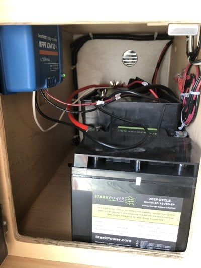
I am new to this forum. I just purchased a FWC Fleet Shell last week and am looking to install a Victron SmartSolar 100v/20a charge controller. My Shell has the flush mount stove and furnace and two 12vdc batteries. I was thinking of installing the controller in the battery box next to the batteries on the rear wall since it is 1/2 inch plywood with the gray finish on it. The controller will just fit between the battery and the rear wall.
The spec sheet for the controller calls for it to be mounted on a "non-flammable substrate". That has me a little concerned about mounting on the inside of the battery box. The advantage to mounting there is that the wires coming from the outside connectors for solar panels end inside the battery box. Also the spec sheet mentions that the ambient temperature of the controller should be within 5 degrees C of the batteries.
I am planning to use a 200 watt panel so I guess I could use a 75v/15a controller. I was not planning to use the load control part of the solar controller.
Do any of you have experience with Victron solar charge controller and have any recommendations on installing one? Any pictures you could share?
Thanks.
 From the video instructions and after cutting the wires, I believe it's telling me to connect the end coming from the Wago connectors to the PV terminal on the MPPT and then take the other end and connect them to the battery terminals on the MPPT. Does that sound right?