Improved Control Panel Teaser

Quick update on this project - parts are in and assembled. I need a nicer knob, but otherwise it is getting close to being installed.
 

Attachments

  • IMG_0007.jpg
    IMG_0007.jpg
    111.8 KB · Views: 338
  • IMG_0009.jpg
    IMG_0009.jpg
    108.4 KB · Views: 348
Very nice! I see the 4WC logo sticker on lower left of the panels; is this a FWC future product?

Thanks,

Phil
 
No. This is a totally unauthorized use of the FWC logo for my personal project. I am in no way related to FWC (besides being a happy customer).
 
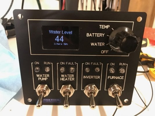
The new control panel is installed, but not entirely finished. I will need to wait until it is a little warmer to fill the water tank and calibrate the water level sensor. But everything else seems to work well.
IMG_0020.jpg

I had to enlarge the opening for the stock FWC control panel a little to make room for the back part of the switches, but this is entirely reversible. The switches left to right control:

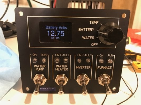
1. The water pump - blue LED light is on when power is going to the pump and red run light is on when the pump motor is running. If the pump runs dry it is sometimes hard to hear that it is running, so the red led would let you know.

2. Water Heater - blue LED when water heater switch is on, red led comes on with ignition/relight just like on the Atwood switch. This was one of my motivations for this upgrade. We left the water heat on on several occasions because it was super hard to tell with the original switch which way was on/off and there was no indicator.

3. Inverter - blue LED when inverter is on and red LED for a fault (over current, low battery etc). My 300W Victron inverter is buried in a cabinet so you can't see the status LEDs on the unit itself.

4. Furnace - blue LED when furnace is on, red LED when thermostat is calling for heat. It is nice not to have fiddle for the tiny slide switch on the side of the thermostat itself.

The display shows battery voltage (redundant as I have a Victron BM-700 battery monitor as well), higher precision water remaining in gallons, and temperature of the water tank, which is useful in the winter.

I converted the hole from the original hot water heater switch (above left of control panel) to a blue seas 12v outlet (or USB charger). The panel is mounted in a somewhat awkward spot form the factory, but as the wiring and hole were already there, I kept it there. The only convenience it give is that it is easy to reach from bed.
IMG_0021.jpg

My Victron battery monitor and MPPT control panel are in a more convenient location.
IMG_0022.jpg
 
Rando, extremely nice setup.

There is one thing I am confused about switch1
Red vs. Blue light
If power is going to the pump it is blue
If the pump is running the light is red

This I where I scratch my head and ask... If power is going to the pump isn't it then running.
 
Bill D said:
Rando, extremely nice setup.

There is one thing I am confused about switch1
Red vs. Blue light
If power is going to the pump it is blue
If the pump is running the light is red

This I where I scratch my head and ask... If power is going to the pump isn't it then running.
The pump has a pressure switch - when you turn the power to the pump on it pressurizes the output side, then the pump shuts off. If you turn on the faucet, the pressure drops and the pump starts. You really only need the blue LED that reminds you that the power to the pump is on. However, if you run out of water in the tank then the pump cannot build pressure on the output side and will run dry continuously. This has only happened to me once, and I noticed the pump was running continuously when the furnace shut off and it became quiet in the camper. If you see that the red stays on for more than a few seconds, you know that you have a problem. Not a really critical addition, but it also helps with the feng shui off the control panel layout.
 
rando said:
The pump has a pressure switch - when you turn the power to the pump on it pressurizes the output side, then the pump shuts off. If you turn on the faucet, the pressure drops and the pump starts. You really only need the blue LED that reminds you that the power to the pump is on. However, if you run out of water in the tank then the pump cannot build pressure on the output side and will run dry continuously. This has only happened to me once, and I noticed the pump was running continuously when the furnace shut off and it became quiet in the camper. If you see that the red stays on for more than a few seconds, you know that you have a problem. Not a really critical addition, but it also helps with the feng shui off the control panel layout.
That makes sense. I never really thought about the way the pump pressure switch works. But now that you mention it, it makes perfect sense and is very logical. If it didn't work in this manner the pump would always be pumping needlessly all the time when powered. It only needs to pump while you are drawing water.
 
rando said:
No. This is a totally unauthorized use of the FWC logo for my personal project. I am in no way related to FWC (besides being a happy customer).
Now I am bummed, Rando! In my innocence I assumed you were a beta test site for FWC. Having bought TWO brand new FWC campers in the last four years I obviously am a "happy camper". BUT their stupid little red lights for battery and water are ridiculously inaccurate. :(
 
Rando,

Nice work. Would love to see a schematic and parts list. :)

Wondering why you chose toggle switches instead of lower profile rocker switches?

Thanks for sharing this.

Craig
 
There is not much in the way of a schematic - the brains is an Adafruit Metro Mini:
https://www.adafruit.com/products/2590

The display is an Adafruit OLED driven in SPI mode:
https://www.adafruit.com/products/938

The water level sensor is the capacitive type:
http://www.newprovidencemarine.com/product_sensor.html#foil

The code is extremely straight forward.

I went with toggles as they are sturdier than rockers and give good tactile feedback - I can easily find the pump switch without looking at the panel or the furnace switch in the dark. They also take up a lot less space in the panel than the standard carling rocker switches.
 
My toe/foot has hit the rocker type switch for the water pump and turned it on, on more than one occasion.
Same with the rocker style switch for the refrigerator fan, coming in and out of the back door of the camper.

At least they don't hurt, if you accidentally hit them.
 
rando said:
There is not much in the way of a schematic - the brains is an Adafruit Metro Mini:
https://www.adafruit.com/products/2590

The display is an Adafruit OLED driven in SPI mode:
https://www.adafruit.com/products/938

The water level sensor is the capacitive type:
http://www.newprovidencemarine.com/product_sensor.html#foil

The code is extremely straight forward.

I went with toggles as they are sturdier than rockers and give good tactile feedback - I can easily find the pump switch without looking at the panel or the furnace switch in the dark. They also take up a lot less space in the panel than the standard carling rocker switches.
Rando,

Thanks!

Craig
 
Quick update on this - I have the new water level sensor installed and calibrated. Due to the nature of the foil sensors, you don't get a whole lot of sensitivity on either extreme (ie you have to use a couple of gallons before it starts going down, and when it reads empty you still have 2 gallons left), but it works well in middle - about 1 gallon resolution. One other thing to note, the FWC spec on the fleet flatbed water tank is wrong, it is a 15 gallon tank, not a 20 gallon tank as advertised.
 

New posts - WTW

Back
Top Bottom