Low cost DIY Lithium camper batteries.

Thanks rruff
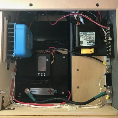
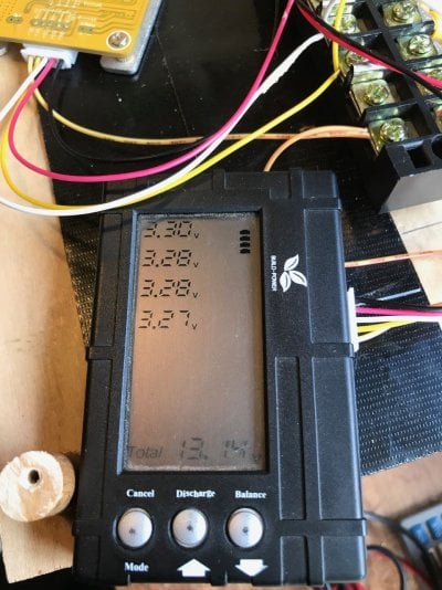
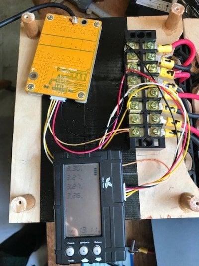
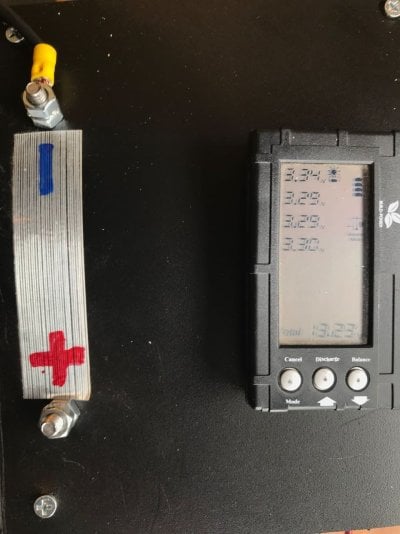
I am a noobie with all the self doubt and so am overly cautious. I am getting tired of looking at the battery 95% done sitting on my work bench so I decided to bring it up to 99%! I reread a few times the direction Rando had given me on wiring and went ahead and attached the two BMS/monitor I have ....I think.... done okay in that I haven't fried anything.
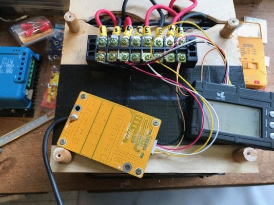
I am at the point where I have the negative wire from the battery management board.... which I believe will be the battery post wire... and the positive battery post wire I think comes straight from the terminal block + (?)
I have to make the two "posts".
If so I am "done" the making and will work on the install. As I have a three week trip coming in July I might hold off and depend on my current AGM set up for the trip.
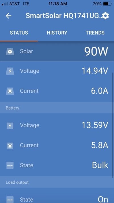
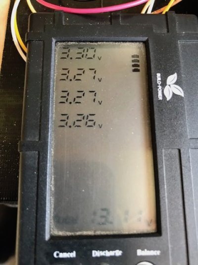
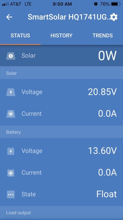
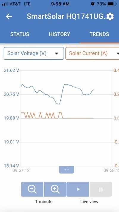
I have to learn how the solar controller is programed for charging the battery to the right voltage (float and max charge). I am only familiar with how the AGM batteries are maintained. Here are a couple photos.
 

Attachments

  • IMG_7890.jpg
    IMG_7890.jpg
    221.6 KB · Views: 67
  • IMG_7891.jpg
    IMG_7891.jpg
    150.2 KB · Views: 290
Attached the Victron controller to battery and a 90 Watt panel. Set up the iPhone app and connected bluetooth to controller.
Set the battery management to 3.7 V limit for each cell (14.8) and drain at 3.
Set the float on the controller to 13.6 V
Set the Absorption to 14.8 (Not sure ...is this the Bulk charge?)

The battery monitor has not changed readings.
I find it odd that panel is indicating 0 Watts
Attached find screen shots of there Victron App

Any advice appreciated as at this point not sure what am looking at.
 

Attachments

  • IMG_7892.jpg
    IMG_7892.jpg
    77.6 KB · Views: 56
  • IMG_7893.jpg
    IMG_7893.jpg
    82 KB · Views: 60
  • IMG_7894.jpg
    IMG_7894.jpg
    51.5 KB · Views: 70
  • IMG_7896.jpg
    IMG_7896.jpg
    56.6 KB · Views: 64
buckland said:
Any advice appreciated as at this point not sure what am looking at.
Sorry I can't help you. I haven't even put my batteries together yet, or played with them in some time.
 
That's Ok I'll just be patient and wait for someone who fiddles with this stuff to know. The panel has been in the sun for 3 hours and the battery has not charged a bit....I must have some setting set that is keeping it from happening​. I like the scientific method rather than the method of "push all buttons and see what happens".... I am amazed I got this far!
I also am not sure why I need the two Battery Management systems... maybe that is the cause?
 
Buckland,

The Victron app display shows that the panels are working and outputting voltage (20.85 V).
The battery part of the display shows it is fully charged (13.6 V) and in float mode thus no current is flowing. If you have a small load you can put across the battery you should see the battery voltage drop and current start to flow.

Did you go into the app settings and make sure the various parameters for your particular battery are set correctly (it seems so but never hurts to double check)?

whoops, I just double checked the settings you posted

Set the battery management to 3.7 V limit for each cell (14.8) and drain at 3.
Set the float on the controller to 13.6 V
Set the Absorption to 14.8 (Not sure ...is this the Bulk charge?)

Those do not look correct to me (I use a lead acid battery) I believe LiFePo4 cells are 3.65 V each. A 12 V LiFePo4 battery would use 4 cells.

4 cells at 3.65 V = 14.6 V I think this is what your float voltage should be.

I am not sure but I think the absorption charge setting should be around 14 V

Hopefully Rando or someone else familiar with LiFePO4 will comment.

Since you have the float setting programmed for 13.6 V, the Victron charge controller thinks your batteries are fully charged already hence no current flow.
 
ckent323: 4 cells at 3.65 V = 14.6 V I think this is what your float voltage should be.

I think I did 3.6v max while charging and they settled to ~3.3v fully charged. That's 13.2v for 4 in series.
 
are these what you guys are using?

Manufacturer: Guangzhou Fullriver Battery New Technology Co., Ltd.
Model: 32700Fe
Nominal Voltage: 3.2 - 3.3 V
Nominal Capacity: 5400 mAh
Energy density: 125 wh/kg; 300 wh/l
Charging current: 3.3 A Max.
Discharging current: 9.9A continuous
Operating Temperature:
Charging: 0° to 45°C
Discharging: -20° to 60°C
Cycle Performance:
>2000 (80% of initial capacity at 0.2C rate, IEC Standard)
2 times more than NiMH and 10 times more than SLA
Dimensions (DxH): 32.3mm (1.27") x 72.0 mm (2.83")

I think these are 3.65 V per cell peak voltage and 3.2 V - 3.3 V per cell nominal voltage. (page 1 - Post #4 in thread).

Anyway going back to the first few pages of the thread I see that rando chose to derate the charging to 90% to 95% of SOC and limit charging to about 3.2 V per cell (page 8 - post # 72 in thread). No criticism just an observation - I am no expert on these.

Probably best to ignore my float voltage setting comment - my comments were simply intended to stimulate your thinking about the details of the settings.
 
Okay.. the other strange thing is the battery balance monitor (not Victron) is indicating my battery only had 13.13 V
3.32, 3.28, 3.27, 3.26.
I just flipped on the balancer and I believe it corrects at .05 per 10 minutes. ? Will leave it on for a couple hours and see what happens.

Update after three hours .... no change in any cell all exactly the same..... hmmmmmm

Also wondering why the BMS says 13.11 V... the Fluke says 13.13 V and the Victron app says 13.6V. ?
 
Sorry for the delay on this - I am off on a field project.

Your balancer set up looks to be correct - and the cells are in decent balance for not having been actively balanced previously. If you press the balance button on the balancer you should see a little scale icon (aka a balance) appear by the higher voltage cells. Just be aware that this balancer only draws 0.1A from the cells and is therefore it is SLOW to balance such a big battery pack - as in it could well take several days or longer to bleed down the higher voltage cells. As long as you see the scale icon though it is working.

There is definitely something not quite right with your solar system. It almost looks like it is not connected to the battery and that it is just pulling the output up to the float voltage. I also don't see in the photos how you have the BMS circuit board hooked up to the batteries overall -ve and +ve terminals (the two end most screw terminals on the screw terminal block)? Has that been done?

For now you can just hook the Victron battery connection directly to the pack (without going through the BMS circuit board) and it should work for now. But you should eventually hook it up through the BMS at some point as this provides an extra level of protection if something were to go wrong.

For the charger set points - lithium batteries don't like to be float charged, so set the float voltage to be just a hair above the fully charged battery voltage - say 13.3V. This way any loads will pull of the solar system first, but you won't really be float charging the battery. I set my bulk and absorption to be pretty low at 13.8V as I rarely use the whole battery capacity and I would prefer it to last longer than to get that last 10% of charge. Make sure equalization and temperature compensation are turned off.
 
Quote and answers:
Your balancer set up looks to be correct - and the cells are in decent balance for not having been actively balanced previously. If you press the balance button on the balancer you should see a little scale icon (aka a balance) appear by the higher voltage cells. Just be aware that this balancer only draws 0.1A from the cells and is therefore it is SLOW to balance such a big battery pack - as in it could well take several days or longer to bleed down the higher voltage cells. As long as you see the scale icon though it is working.
The battery management board (not monitor) is hooked up exactly as the monitor BMS (why do I need both? do they do the same thing?)The board however has the neg- 10 gauge wire soldered to the board. That runs to the Victron battery neg.-. I followed your directions for balance wires that clip in with plug and go to the terminal board exactly like yours except the last balancing black wire from the clip goes to the negative on the terminal and orange to the positive. the other three are in-between the four packs.
On BMS monitor I set the drain minimum V to 3.0 and the top at 3.3 V. I have hit balance and it ran for hours w/o anything changing.

There is definitely something not quite right with your solar system. It almost looks like it is not connected to the battery and that it is just pulling the output up to the float voltage. I also don't see in the photos how you have the BMS circuit board hooked up to the batteries overall -ve and +ve terminals (the two end most screw terminals on the screw terminal block)? Has that been done?
I have the panel connected to the PV on the Victron. I installed the Victron iPhone app and it shows panel and battery. I have not figured out all the settings. I did set the battery type to LiFePo4. I set the float to 13.6 .... I can't find anywhere where it sets Bulk. The last question you ask I thin I answered above.

For now you can just hook the Victron battery connection directly to the pack (without going through the BMS circuit board) and it should work for now. But you should eventually hook it up through the BMS at some point as this provides an extra level of protection if something were to go wrong.
Both BMS boards are attached. The neg soldered to the board goes to the Victron battery negative - and the positive on the terminal block to the Vicvtron Pos.+

For the charger set points - lithium batteries don't like to be float charged, so set the float voltage to be just a hair above the fully charged battery voltage - say 13.3V. This way any loads will pull of the solar system first, but you won't really be float charging the battery. I set my bulk and absorption to be pretty low at 13.8V as I rarely use the whole battery capacity and I would prefer it to last longer than to get that last 10% of charge. Make sure equalization and temperature compensation are turned off.

I will change the float to 13.3. I do not know how to set the Bulk on the Victron but I think I have seen the page with the absorption setting on the Settings page. I will photo that here next. Yes the equalization and temp compensation are off.

Thanks again for your guidance. It is getting exciting to think this might just work! Also great not having to maintain the battery during cold season. I believe you said I should bring the battery down 3 V per pack for storage and forget about it until Spring.
 
Here are the Victron app battery settings page. Note I set the float and the absorb volts but then when I select the LiFePo4 for battery type it changes the settings. IMG_7970.JPGIMG_7971.JPG
 
Based on what you are seeing on the Victron and this photo assuming it is how it is set up:
index.php


It appears that your battery isn't actually connected to its output. You need to run a heavy (10AWG) wire from the 'B-' terminal on the BMS board to the terminal with the 'black 4' wire on the terminal block. The main output terminals of your battery will then become the 'red 1' terminal on the wiring block an the 'P-' terminal on the BMS which already has a wire.

The primary purpose of the BMS is to protect the cells in your battery from over or under charge. It does this by measuring the voltage of each cell using the skinny wires connected to the white connector. These wire are only to measure the voltage and aren't supposed to carry any current. If the BMS senses that any individual cell is over or under voltage it will disconnect the heavy negative terminal (that should run through the BMS) from the battery and save it from being damaged. Yo are using a different BMS to the one I am using but it may have balancing as well, in which case the back box is a bit redundant. What the black box provides is a quick way to see where your cells are, how well they are in balance and a way to manually force a balances.

When you switch the battery type on your Victron to LiFePO4, all that does is load some pre configured settings, which then over rides the settings you entered - you would do better to use custom settings for your usage.
 
PS you probably want to make the 'absorption time' shorter, like an hour. The ideal charge profile for a lithium battery is to bring it up to the specified bulk voltage (13.8V in this case) then shut off the charger, no absorption and no float charge required, which is one of the big advantages of lithium.
 
Got it and done. Appreciate your sticking with the explanations. I am starting to 'get it'...all the parts are making sense and though understanding is shallow compared to electrical folks... I have learned a bunch. This will be a longterm solution for power.
I assume the Fluke reading of 13.13 V and the BMS montitor with 13.13 V being different from the Victron app reading of 13.6 V of the battery is no big deal? All in all a relief it works!
I now have to do some cutting (metal rollover couch support on front wall) to be able to get this battery pack into the Eagle battery box.
Construction work I feel good about...it won't be a big job.
I also assume that it would not be a big deal to have the Victron horizontally mounted instead of vertically (as stated in the install paper). Just need to put it where it will fit in that battery box corner.
I hope that others, who might be on the fence of whether or not to try this, will feel confidence to give it a go. It currently is an economical way to upgrade batteries when the AGM start to fade and they should last a long time. It is also good to learn new things even though they seem daunting. I certainly went through a lot of solder! Well worth it.
Thanks Lars
 
If everything is connected correctly the Victron and the BMS/Fluke should now read the same voltage (+/- 0.01).
 
And that happened today! I finished the set up and plugged in the solar panel and suddenly the monitor started to show voltage changing as the Victron was on bulk charge. Over an hour they settled down and were closer to 3.3 each. I put on the balancer and hope that they will converge. I am very excited that things are coming together. I have bought a shunt and voltage display .... next step after install and have a vague idea (YouTube) how to set this up to monitor in and out usage to battery and load. Sure wish I learned this awhile ago.
 
The next stage is the shunt and battery monitor. Here are a few photos ...the first is the BMS monitor that now seems to be responding well.
 

Attachments

  • IMG_7978.jpg
    IMG_7978.jpg
    137.9 KB · Views: 59
  • IMG_7976.jpg
    IMG_7976.jpg
    10.7 KB · Views: 66
  • IMG_7977.jpg
    IMG_7977.jpg
    136.6 KB · Views: 64
As mentioned in the shunt thread, the Eagle has landed! I just decided to wire the shunt for battery and finished the install. It seems to work (yeah I am always amazed ). Thanks to Lars and Vic especially for your help. It took a year all told as life took a detour but getting out those two 55 pound AGM batteries and then putting the new 42 pound LiFePo4 battery in felt real good. I will plug in the portable panel soon and see how that works. The Victron app is real nice to see what is happening ... how much each item draws when running. The shunt monitor works as well so all in all I could not be happier. I could not have even attempted this without the help and I have learned a lot in the process (one of which is I am not a natural at soldering :sneaky: ).
Not that I know much but if anyone attempting to make the battery needs to ask basic questions feel free to ask.
 

Attachments

  • IMG_8038.jpeg
    IMG_8038.jpeg
    210.2 KB · Views: 67
  • IMG_8040.jpg
    IMG_8040.jpg
    81 KB · Views: 65

New posts - WTW

Back
Top Bottom