Low cost DIY Lithium camper batteries.

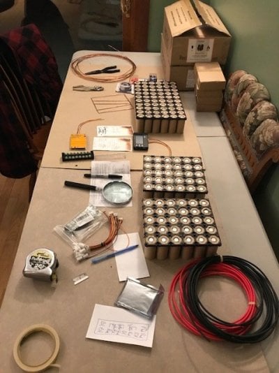
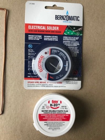
Well I went all in... ordered the batteries and the sundry items needed (with the help of this thread starter! BIG Thanks). Have to get the higher wattage iron, flux core solder and flux and a shrink wrap hot gun (Craig's list $15) .... I have a hot glue gun to hold things together.
I have been on the sidelines watching this idea...thinking it was too much for me without the electronic background but with some help I think it is a great opportunity to improve the camper....save enough weight to equal a big dog and her food! That is the beauty of WTW... sharing ideas and expertise! The stuff should all be here in 2-3 weeks and then I will repost with the assemble table photos and requests for advice. A great winter time project.
 
This is a great thread. I expect another five years out of my current agm's but then I'll join the bandwagon.
 
Another question .....I opened the wire I ordered and it is not solid but multi strand .... is that a problem?
Rob
 
Besides the wire type question I also noticed the 5 wire connectors for the battery balancer and the battery voltage monitor are very thing wires and wondered from the photos you posted if you changed them somehow? Attached are the two units I got from the links sent.
Also I will have figure out the wiring on the balancer.. i.e. where to solder the wires going out of the balancer board ... as I do not know if the -C and -P holes at the opposite end are what I am looking for. Or if it is the pairs of wicked small + and - holes of which there are two sets on either side of the clip plug. I also realize I don’t have the 30 amp block jumpers I’ll need for the terminal block...


IMG_3658.JPG


IMG_3656.JPGIMG_3654.JPGIMG_3655.JPG
 

Attachments

  • IMG_4147.jpg
    IMG_4147.jpg
    81 KB · Views: 59
buckland said:
Another question .....I opened the wire I ordered and it is not solid but multi strand .... is that a problem?
Rob
Stranded wire is what you want for everything except solder the actual batteries together. Stranded wire is way more flexible and easier to work with than solid wire. The exception is soldering the batteries together where you want the rigidity of the soled wire, and for it not to wick up all your solder.
 
The thin wires for the battery balancer is what you want. No real current flows down these wires, it is really just to check on the voltage of each battery pack and bleed of a little bit of charge from any that are higher than the rest. I think the balancer only draws ~100mA maximum.

Your battery protection circuit is a little different to mine - yours connects or disconnects the negative terminal of the batteries from the camper in an under/over voltage situation. From the diagram on the back and reading the ebay description, you want to wire it up as follows:

B-: heavy gauge wire to the negative terminal of the first battery pack. This is the wire that all the negative charge and discharge current flows on. I think we talked about using 10 or 12 AWG.

C-/P-: Heavy gauge wire to the negative terminal of the input/output to the camper. If you are over/under voltage the protection circuit will disconnect this terminal, shutting down the battery.

Your system uses the same balance connector as the battery balancer, which is nice! You connect the small wires from this to the junctions between each of your battery packs according to the diagram on the board. As I mentioned before, these small wire are really just to keep an eye on the voltages of each individual pack to make sure they don't get out of balance and that no individual pack voltage is too high or too low.

This is pretty good diagram of how the whole thing should be wired up, the only difference is the fat wire coming out of cell 4 doesn't got to your protection circuit, it goes straight to your battery-to-camper terminals:

51329da8-c731-4789-8824-4fe255ae83e4.jpg


buckland said:
Besides the wire type question I also noticed the 5 wire connectors for the battery balancer and the battery voltage monitor are very thing wires and wondered from the photos you posted if you changed them somehow? Attached are the two units I got from the links sent.
Also I will have figure out the wiring on the balancer.. i.e. where to solder the wires going out of the balancer board ... as I do not know if the -C and -P holes at the opposite end are what I am looking for. Or if it is the pairs of wicked small + and - holes of which there are two sets on either side of the clip plug. I also realize I don’t have the 30 amp block jumpers I’ll need for the terminal block...


[attachment=30226:IMG_3658.JPG
[IMG]http://www.wanderthewest.com/forum/public/style_images/master/attachicon.gif[/IMG]IMG_4147.jpg


attachicon.gif
IMG_3656.JPG
attachicon.gif
IMG_3654.JPG
attachicon.gif
IMG_3655.JPG
 
Also to add - you can put two balance connectors on (each wired the same way, so in parallel with each other) so you can have both your protection circuit and the voltage meter/balancer plugged in at the same time.
 
Thank you for the explanation. I hope you have patience.... as my knowledge base is low ...some of the things you might assume I already understand ...well I probably don't. For example: In the above drawing, the five leads (4 red, 1 black) I assume it corresponds to the black wire in the bat bal. clip plug and the red, white, yellow, and orange correspond to all the reds in the diagram.

* On the drawing above the red (+) coming out (on the left) of the battery balancer is attached where on the board I have?
In the photo of My Bat. Bal. I do not see a P+

* These holes B- and C-/P- ... does one use a small bolt and nut or simply wire through and solder?

* and which of the two: C- or P- does one solder to?

As you can see this is my first rodeo.
 
Answers below in bold.....


buckland said:
Thank you for the explanation. I hope you have patience.... as my knowledge base is low ...some of the things you might assume I already understand ...well I probably don't. For example: In the above drawing, the five leads (4 red, 1 black) I assume it corresponds to the black wire in the bat bal. clip plug and the red, white, yellow, and orange correspond to all the reds in the diagram.
Correct, but ignore the colors on those wires and follow the little diagram printed on your board - the orange one goes to the negative terminal of cell/pack 1, yellow to the junction between pack 1 +ve and pack 2 -ve, the white to pack 2 +ve / pack 3 -ve, red wire to pack 3 +ve/pack 4 -ve, and black wire to pack 4 +ve. What I did on mine is bring all the wires from all the packs (8 in total) up to the 8 circuit junction strip on top of the battery pack and then use jumpers between adjacent terminals to put them all in series. This also made it super easy to attach the balance wires.

* On the drawing above the red (+) coming out (on the left) of the battery balancer is attached where on the board I have?
In the photo of My Bat. Bal. I do not see a P+
That doesn't go to anything on your board - it just goes straight to what ever you are using for your battery-to-camper connection.

* These holes B- and C-/P- ... does one use a small bolt and nut or simply wire through and solder?

Wire through and solder.


* and which of the two: C- or P- does one solder to?

Use which ever hole fits your wire better, which is probably the smaller one (P-).

As you can see this is my first rodeo.
 
[SIZE=16pt]Hi Rando, Hope you don’t mind some input since this is your thread.[/SIZE]
[SIZE=16pt]In regards to the ebay protection/balance board Buckland is using, hooked up as only a balance board, you’re using only half of the board. I use these a lot for small battery projects around here and the 30 amp protection portion of the board works neat. One note you might consider is the balance current of those boards is 45ma max. For a 100+ amp hour battery bank a 45ma balance current is insufficient. [/SIZE]

[SIZE=16pt]The same company that makes the 30 amp board also makes one rated at 100 amps. I bought a couple of those to play with and found those also have insufficient balance current. The balance resistors on those boards are 100 ohm, I added 13 ohm resisters in parallel and got a balance current of just over 300ma which seems to work great on the 100AH battery. My two cents…[/SIZE]
 
All input is welcome!

The automatic balance feature on these boards is not really of much use as it doesn't kick in until you reach a charge voltage of 14.6V, which my battery will never see and as you point out the balance current is really low.

That is why I added the '3 in 1' LCD battery balancer to my pack. It gives quick feedback on the need to balance, the ability to balance at any voltage and a slightly higher balance current. I am actually not sure what the current is, but in testing it, it got reasonably warm, so probably a decent fraction of an amp at 3.2V.

However, I have found that if you keep the away from the 'knees' in the charge/discharge curve, balancing becomes much less of an issue, in fact in the 4 months or so I have been using my battery all the cells are within 0.01V of each other, so no need to balance.
To keep away from the 'knees' I only charge the battery back up to 90 - 95% SOC, by setting my charge controller to shut off at 13.8V. I am missing out on some of my capacity, but even 100Ah of my 150Ah battery is more than I have ever needed. It is worth it to me to avoid out of balance issues.
 
Well this is fun! My dad use to say... “ heck ...if you are on thin ice you might as well dance!” This is a steep learning curve for me and that’s okay... I have a winter to get it right. Thing is as a teacher of thirty years I have always tried to to find the misconceptions or holes in the knowledge base of my students so I could then patch or bridge their understanding in the topic being covered ( not possible for me in this case!) .... this lack of foundational knowledge will haunt me in this endeavor but I am determined to suss it out and in the areas of complete ignorance try to work backwards with what I am hearing to understand the “why”of it. I appreciate your expertise and with it hope to learn from it. Right now I am just bending a lot of solid copper wire which is right at my level of fun! Thanks again for the input.
 
Bending and soldering the copper wire is by far the hardest part, so you are almost there!
 
Stick with me ...I’ll be back after I get this ‘cage of wires’ built ... eight of them! Flux... I bought the plumbers kind and ai bought leaded solder 40/60....
I’m supposed to pre-flux the posts ....drop bead of solder on them.... pre tin the copper at each of the 30 spots ...then lay the cage on top of the batteries and drop solder on each spot? With more flux? ( this could be fun if not worried I’ll fry the batteries!)
After I get through this hoop ...I’ll be back for more tutelage.
 
Honestly, acid flux will work much better in this situation, you just want to clean it off when you are done with a wipe from a damp cloth. K6ON is right, the general rule is not to use acid flux for electronics work, but to use 'no clean flux' which is normally rosin core flux. A However the heavy duty soldering you are doing here is more akin to pipe soldering than mounting a resistor on a circuit board, and you really need all the assistance you can get with bonding the wire to terminals. Acid fluxes are much more aggressive than rosin fluxes. A more precise rule would be to use the least acidic flux in order to get the job done, and in this case an acidic flux works much better. Again, just be sure to wipe it off once you are done. But use your own judgment on this, I am just saying what worked for me and my reasoning.

As for pre-tinning the wire, I did this as I soldered the wires. I soldered each piece of wire to the first battery in that row, then laid it over the rest of the batteries and quickly tinned just the spots were the wire would be soldered to each battery. My process was:

1. Clean all the terminals with alcohol.
2. Apply a small amount of flux to each cell using a q-tip.
3. Make a ~1/4" pool of solder on each cell, applying just enough heat that the solder flows, and doesn't bead on the surface. This is the hardest step, it took about 5-10s of heat per terminal.
4. Clean all the terminals again.
5. Solder the wire to the first terminal in a row.
6. Tin the wire with solder where it will touch each subsequent terminal
7. Move down the row soldering the wire down, which is extremely easy as both surfaces are tinned at this point.
8. Check each row and re-work any joints that don't look great.
9. Rinse and repeat.
10. Finally wipe everything down again and inspect your work one last time.

It seems like a lot of steps, but it is production line work and goes fast.
 
Thanks on the reassurance. Here are a couple shots of the solder and flux I bought. I did order a 100 W iron that should be here on Monday. I will be bending the wire as I noticed how you did. From your above directions then you suggest soldering the 'box' copper wire to the end corners then the ones along the sides, followed by the three straight cross pieces? I am a true believer in the 'order of operations' (never put your shoes on then your socks). I will spend tomorrow cutting and bending the eight sets of wire for the four packs.
 

Attachments

  • IMG_4149.jpg
    IMG_4149.jpg
    71.7 KB · Views: 69
  • IMG_4152.jpg
    IMG_4152.jpg
    78.6 KB · Views: 72
  • IMG_4154.jpg
    IMG_4154.jpg
    77.1 KB · Views: 67
buckland said:
Thanks on the reassurance. Here are a couple shots of the solder and flux I bought. I did order a 100 W iron that should be here on Monday. I will be bending the wire as I noticed how you did. From your above directions then you suggest soldering the 'box' copper wire to the end corners then the ones along the sides, followed by the three straight cross pieces? I am a true believer in the 'order of operations' (never put your shoes on then your socks). I will spend tomorrow cutting and bending the eight sets of wire for the four packs.
I don't think it is particularly critical how this is done. I actually soldered each 6 cell row with a piece of wire and left enough extra wire at each end that I could bend it up to make contact with the next row. Essentially each piece of wire was a wide, short U, with each end connecting to the next row. But I think the layout you have would work just as well - it is good to have redundant paths to each cell so that if one connection failed, the current could flow on a redundant path.
 
Back
Top Bottom