Truck Camper Front Rack & Cargo System Help

Simpleman (shanz3n5)

Advanced Member
Joined
Sep 26, 2013
Messages
78
Location
corona, ca
Looking for all good ideas and tech issues, to build up a front cab to front bumper rack and cargo carrier.
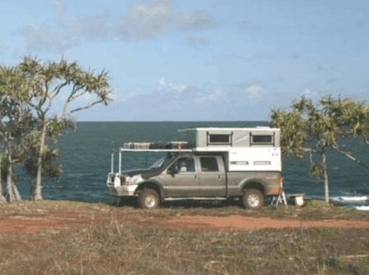
I know this isnt a typical set up or solution. I will mostly be using it for long haul and long base camp stays. Here is one photo of the general idea i found through google images. Unknown owner.
Im having an Aluminess front bumper made at this time, and will be mounting a 3 receiver front hitch to frame under it.

Running 2 vertical uprights and horizontal supports is the easy part.
How to attach the horizontal supports to the rear is my main concern
Ideas:
1. Low profile headache rack. Concern: truck flex point between bed and front bumper. twisting rack.

2. Yakima Base Rack (cab roof tower set and bar. No capacity specs and very pricey). Is the the capacity (when i find it) in the bar or the tower shoes.

3. Thule rack. Similar issue but the posted a weight capacity of 165. I'm sure to exceed that weight with basket and gear, but they have a bar/tube that maybe i could stiffen.

so im open to ingenuity and ideas or if there is a system already out there
thanx

full
 

Attachments

  • photo.JPG
    photo.JPG
    59.3 KB · Views: 176
Some thoughts:

As you wrote the relative motion between the bed and the cab will be an issue so don't attach to anything connected to the bed (e.g. camper).

The best connections would be to the frame at both ends if possible (maybe to the front bumper that is directly attached to the frame and perhaps supports that come up and around the cab from the sides or from the bed side betwen the bed and the cab?).

Estimate the maximum load you will carry. The loads, beam deflection (motion) while under way and resultant fatigue to the beam and the beam connections should be considered (dare I say engineered) in order to size the entire assembly appropriately.

Once you know the load you (or a mechanical engineer) can estmate forces based on anticipated worst case use (pavement, potholes, washboard roads, whatever). Once the forces are in hand you can look at material information and calculate minimum crossectional area for a given material and beam, riser or connector size.

I am not a mechanical engineer (but I am an engineer) and looking at the picture I cannot tell how robust the cargo carrier is but I do see long beams and not insignificant risk of damage and inconvenience if a beam or joint coupling (connector) failed on a bumpy road while underway. Never mind the stuff falling off and where you would subsequently put it, the windshield could be broken or worse.

Be careful and Good luck

Regards,

Craig
 
wow that was great feed back. i am no engineer either, unless a fire engineer/operator and heavy equipment engineer/operator count. HA. But seriously. those thoughts are whats on my mind. Cab frame section to bumper frame end. i was in industrial and aircraft fabrication for a long time so i do know the results of fatigue. i will probably use your advice with some trial and era on my end .... ie, starting with some conduit bending and moc up and bolt on. to watch flex and travel. i dont plan on getting rid of the truck any time soon. and as much as i see loads on top of the flexible , 6 point only latch FWC roof. Im very hesitant to do with a load.
Thank you very much for your feed back. It is greatly appreciate.
 
Taken me a bit to get back to this. The cab rides on rubber bushings to isolate it from road induced NVH in the chassis. The bed does not have this, at the most it has some polymer or rubber sheets between it and the chassis mounts that it bolts directly to.
So the bed will move more with the frame than the cab will. Either put all of the load on the cab, or put all of the load into the chassis but do not put part of the load on the chassis and part of the load on the cab. I would not put any load on the camper as it isn't designed for those loads and it will move a little differently than does the bed.

If you can design and fabricate structure to pick up the forward most bed mounting bolts that then come up behind the cab and under the camper that would be my suggestion. Depending on truck/camper configuration and the total load you may have to settle for anchoring to the stake pockets.

The process that you're looking for to size the beams is called a "Shear-Moment Diagram." That will give you a maximum stress, which leads to the minimum Moment of Inertia (w/o any Factor of Safety [FS]). An FS of 2 is good, 3 is better. Beyond 3 is a waste of time and materials unless a failure will directly result in loss of life at which point an FS of 5 is the minimum.
Could go into Fatigue calcs, but if the weight isn't super-critical I myself wouldn't bother and build it from mild steel.
An easy way to get a FS of 2 is to do the Shear-Moment with the total load on one beam and apply the resulting minimum MOI to both of the beams.
 
ntsqd said:
Taken me a bit to get back to this. The cab rides on rubber bushings to isolate it from road induced NVH in the chassis. The bed does not have this, at the most it has some polymer or rubber sheets between it and the chassis mounts that it bolts directly to.
So the bed will move more with the frame than the cab will. Either put all of the load on the cab, or put all of the load into the chassis but do not put part of the load on the chassis and part of the load on the cab. I would not put any load on the camper as it isn't designed for those loads and it will move a little differently than does the bed.

If you can design and fabricate structure to pick up the forward most bed mounting bolts that then come up behind the cab and under the camper that would be my suggestion. Depending on truck/camper configuration and the total load you may have to settle for anchoring to the stake pockets.

The process that you're looking for to size the beams is called a "Shear-Moment Diagram." That will give you a maximum stress, which leads to the minimum Moment of Inertia (w/o any Factor of Safety [FS]). An FS of 2 is good, 3 is better. Beyond 3 is a waste of time and materials unless a failure will directly result in loss of life at which point an FS of 5 is the minimum.
Could go into Fatigue calcs, but if the weight isn't super-critical I myself wouldn't bother and build it from mild steel.
An easy way to get a FS of 2 is to do the Shear-Moment with the total load on one beam and apply the resulting minimum MOI to both of the beams.
Amazing.....and very great full that we still have guys like you around to keep perspective on all our ideas. Yes after a beer or two and some good sense, i took your last reply...... and concur with your knowledge. laying on the ground under your truck with the question of "how is this thing built and way?", brought sensible perspective. So i will design the structure to go frame to frame mount. The rear uprights and cross bar will most likely be on the outside of the C post following the contour of the cab. about 2" of space all around. Bolted to frame at the point where the running board attaches. There is not enough space between the cab and bed and a headache rack would have bed flex. this section would live on the truck. the beams would be removable and adjustable inboard to outboard. Running forward to the front crossbar. The forward uprights and crossbar would be removable and attached to the forward frame mounted double receiver. I thinking 1-1/2" cold rolled steel tubing.
Thanx again for your detailed knowledge and respectful feed back.
John
 

New posts - WTW

Back
Top Bottom