Where To Mount MPPT Charge Controller

Jack

Senior Member
Joined
Nov 18, 2007
Messages
423
Location
Portland OR
Where are folks mounting their MPPT charge controllers?

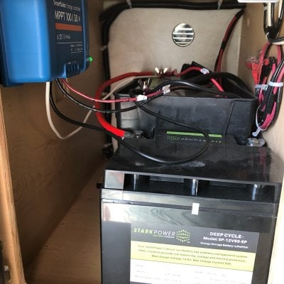
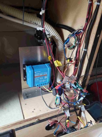
I currently have a 15 A Morningstar MPPT mounted on the backside of the fascia panel (a battery monitor occupies the location of the original Zamp controller). But at 15 A, there's not much heat dissipation and it has no heat sink. I'm looking at the 20 A, the Victron (to add another panel) and it sticks out 2" with the heat sink.

If you are mounting it on the front of the fasia, is bumping into / catching things on it a problem? If you have a 20 A or higher MPPT, how much heat do you find that it dissipates?
 
I have the Victron 100/20 (very nice) I have it mounted inside the battery box on the side wall (vertically) as it does have a heat sink fin on the back. I first mounted it on a small piece of wood 4" x 5" ...then make clips on the wall of the battery box to slide it into position allowing me to remove it easily if I need to remove battery at some point.
 
+1 ... I have a 100/30 Smart Victron, so it is a little bulky, but am happy with it mounted in the battery box out of the way. Can’t speak to heat dissipation but, this summer with 100F+ on multiple occasions, have noted nothing dissimilar. Battery box has 2 small vents probably identical to above post. Mounted directly to wall. Don’t need line of sight w/built in Bluetooth.
 

Attachments

  • E27AFEA8-52C6-4A30-9F32-F9F063179724.jpeg
    E27AFEA8-52C6-4A30-9F32-F9F063179724.jpeg
    265.6 KB · Views: 318
I mounted my Renogy Rover 20 behind and above the couch so I can see it. It's only about a 2' long run to the battery box. I had to do a bit of metal trimming so when the couch is made into a bed it wouldn't pinch wires. It seems pretty good.
 
I forgot to mention that our Fleet is front dinette - so the battery box is a lot smaller and it is stuffed full with 2 Full River 224 Ah batteries.

Six5 - do you notice much heat dissipation from your Renogy Rover 20?
 
There was a lot more room behind the fascia, so I mounted the Victron there. It's has bluetooth interface and supports lithium batteries (for when my AGMs reach there demise)..
 

Attachments

  • CC Location.jpg
    CC Location.jpg
    71 KB · Views: 290
Cabinet.jpg

Jack,

Timely post. I have the same need. I'm just about to buy and install a Victron 100/20 in my 2016 front dinette Fleet. I'll also (finally!) be installing the Victron BM at the same time.

What vintage is your fleet? I have the factory hot water system, so I think I have a different setup and less room than you, but was looking at installing it in approximately the same position (in my photo, in place of the small gray electrical box). Even with the 2 regular factory AGMs, there is no room in the battery box.

I maybe could install it where my current GoPower PWM controller/monitor is mounted, but on the back side of the cabinet fascia. I'll have to make a custom cover for hole left over from the GoPower monitor in any case.

-How easy is it to pop the cabinet fascia off? Any cautions, tips or tricks before I take it off?
-How hot does the controller actually get? Any issues with it being close to wiring, plumbing?
-Did you install the temp sensor, given that there's likely some difference in temp between the kitchen cabinet and the battery box in cold weather? Temps in my battery box are the same as outside in cold weather regardless of temp in the camper.

Many thanks for your advice and experience.
 
I have a 2016 Fleet with a front dinette. I installed a 100/30 Victron controller, a battery monitor and the battery temperature sensor. I have Blue Tooth on the controller and wish I had got it on the battery monitor. I tried the Victron controller in the space where the old controller was but it protruded too far into aisle, which already is close quarters. There is not room in the battery area so I placed it inside the cabinet above the battery box. That cabinet is open at the top allowing air movement. I have felt the controller often to check on heat and have never found it more than slightly warm.
 
I'd agree that the controller only gets warm, not hot. I'd use the temp sensor, especially since you say there is a big temp diff in your setup.
 
Thanks, Desert Scruff and Vic. I may end up mounting in the cabinet above the batteries, though I hate to lose the space. I'll install the temp sensor, too, then. And apologies to the OP for hijacking his/her thread!

Another couple of questions: My two 12V AGM batteries are wired in parallel. Does it matter which of the two battery negative terminals I connect to the BM shunt? I'm assuming I'll just attach to the negative battery terminal that currently carries two negative wires that will be relocated to the other side of the BM shunt (probably solar controller and negative bus bar).

Also, I noticed that I have two positive wires (same as above), but each connected to a different battery. Can I consolidate them on one battery positive terminal, and if so, does it matter which battery (for example, the same battery that will be wired to the BM shunt)?

Many thanks. Really looking forward to finally having a battery monitor and to losing the PWM controller.
 
ideally, you want all the positive wires feeding your system to come off of one of the 12v batteries, and the ground wire to come off of the other battery. That way both batteries get "exercised" the same amount.

Also, the ONLY thing connected to the battery ground should be the shunt. ALL other ground wires go to the far side of the shunt.
 
Vic,

Thanks, very helpful, and gotcha on all* negs moved to shunt far side.

Jeff

*to be clear, except for battery #1 neg to battery #2 neg parallel jumper cable
 
As a follow-up to the questions I asked in this thread, and the helpful answers I received, I'm providing a few details and photos of my install of a Victron 100v/20a MPPT controller and Victron 712 battery monitor in my 2016 Fleet w/front dinette. Hopefully this will be helpful to others with a similar set up.

Because of limited space, I mounted the 100v/20a controller and a 100a breaker in the kitchen cabinet (1st photo). It was very tight. I could have mounted one or both in the kitchen cabinet above the battery box but wanted to save space for kitchen stuff, plus this allowed me to shorten the wiring run by about 3-4 feet. Although it may not be obvious, the breaker is wired between the controller and the batteries.

I then drilled two holes in the bottom of the cabinet and ran the pos and neg wires* from the switch into the space below the converter/charger and directly to the batteries (2nd photo below). (*Note that I used the breaker and a separate neg junction post to consolidate the solar panel and external plug wiring so that I could run single neg and pos wires to the battery box because I barely had space for the two holes owing to plumbing above and existing wiring below.)

I also installed a switch (mounted on cabinet exterior) between the panels and the controller. I upgraded all of the wiring to 8ga except the wiring coming from the solar panels/external solar plug to the controller/switch; I'll upgrade that 12ga wiring along with my flexible panels when the performance of panels becomes sufficiently degraded.

I installed the battery monitor shunt in the back of the battery cabinet (3rd photo below). I added the temp sensor to the monitor because I know that the rather isolated battery box will be significantly cooler than the kitchen cabinet-mounted controller during prolonged cold weather. I made a blank out of aluminum to fill the void in my cabinet left by the prior solar controller and used that to mount the battery monitor (see 1st photo).

I ordered online all of the components and parts from the very helpful people at AM Solar in Springfield OR. Their prices were competitive and I didn't have to source and buy all of the parts separately. Plus they install and service RV solar and use and sell only the equipment they know and trust, they've been in business for years, and were very responsive and answered all of my questions and gave great advice.

Victron controller install.jpg
 
On the Victron MPPT there is grounding screw on the heat sink chassis. What should this connect to?

I have to admit that I'm a bit foggy on grounding on the FWC camper. There is a bus bar next to my fuse box and I'm not sure what it connects to. Perhaps the negative on the battery?

Thanks in advance for your help!
 
Back
Top Bottom