You are using an out of date browser. It may not display this or other websites correctly.
You should upgrade or use an alternative browser.
You should upgrade or use an alternative browser.
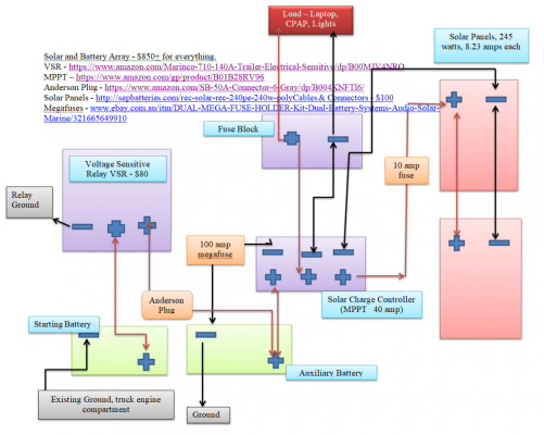
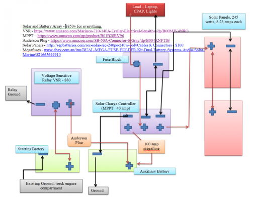
Solar Electrical Array - Laid out correctly?
- Thread starter philos65
- Start date
philos65
Senior Member
Captm
Senior Member
Switch the ground on the camper batteries to the one opposite of the positive connection.
Cheers
Cheers
philos65
Senior Member
Hi Captm:
I'm not sure what you're suggesting. The starting battery is on the left, and the auxiliary/camper battery is on the right in the drawing.
Jeff...
I'm not sure what you're suggesting. The starting battery is on the left, and the auxiliary/camper battery is on the right in the drawing.
Jeff...
To elaborate further, you don't really need a fuse between the panels and the controller assuming the wire is sized to handle the panels in parallel (which doubles your amps). My FWC stock panel wiring was 10 gauge and I added a 12 gauge SAE adapter so with 290 watts of panels I opted to wire mine in series rather than worrying about/upgrading the wire.
Captm
Senior Member
My mistake, I thought the panels were another set of batteries 
Cheers
Cheers
camelracer
Contributors
I think the 100 amp megafuse is overkill. That would require all wiring down stream to be able to handle 100 amps. Fuse it to match the load capacity of the solar controller or the actual load you're anticipating.
philos65
Senior Member
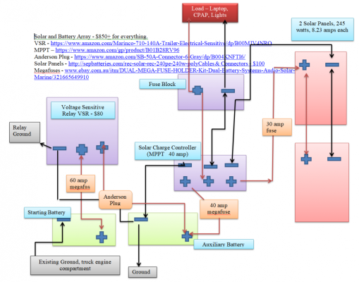
Thanks camelracer. Your comment made me do a deeper web search. Renology recommends a fuse between the panels and controller. And I will downsize the 100 amp to a 40 amp fuse between the controller and battery based on their recommendation.
https://www.renology.com/blog/how-to-fuse-your-solar-system/
I read a bunch of other sites and one of them insisted the solar panels need fusing beyond what renology recommended.
I googled "how to fuse a rv system" and the second entry from windynation was interesting to read. This guy recommended fusing the panel/controller wiring. AM solar says their systems don't fuse the wires between panels and controller.
I revised my drawing to include fuses - probably overkill.
Jeff
Attachments
Fusing solar panels seems to be a common point of misunderstanding. Think for a second about what the fuse is supposed to do (which is really protect wiring from overheating and causing a fire, and to a lesser extent protect equipment). Now ask yourself these questions:
1. Where physically would the fuse be in this system?
2. What wiring would the fuse be protecting?
3. What value fuse would be appropriate, and CAN the current ever exceed that value?
Once you answers these questions I think you will realize why a fuse is pointless in this application.
1. Where physically would the fuse be in this system?
2. What wiring would the fuse be protecting?
3. What value fuse would be appropriate, and CAN the current ever exceed that value?
Once you answers these questions I think you will realize why a fuse is pointless in this application.
I agree with the others, a fuse between the solar array and your mppt controller is not needed. That said, it is convenient to be able to disconnect your panels quickly sometimes.
Ditto with the fuse between the controller and the batteries.
Are you planning to add to your solar capacity at some point? As is, you have 17amps max input and a 40A controller. That seems like overkill.
It looks like you are planning to use a chassis return for the negative connection between the starting and Aux battery banks. I would run a separate wire for that and not count on the chassis for carrying current.
I see only one fuse on the positive line between your starting battery and the VSR. Assuming that your VSR is in the camper (like mine is) you have a long wire going from the engine bay to your camper, through and Anderson plug. Either end of that wire should be fused within a few inches of the respective battery banks. I have a 100A Blue Sea breaker on both ends, one right at the battery before a shunt for my in cab ammeter, and before the Blue Sea ML-ACR/VSR in the camper.
philos65
Senior Member
Thanks for all the suggestions. I feel more confident about how to wire the solar array.
Jeff
Jeff
ntsqd
Custom User Title
I think that a fuse in the solar panel circuit is a desirable thing IF it can be placed close to the panels. Can think of solar panels as being a very odd battery, as they are a power source, and we place a fuse or breaker next to those.
That said, I do not have a fuse in that circuit.
The ground wire for the VSR is not just a ground for its contact coil. It is also the Reference Ground used to determine when to open and close. It should be connected to a very good ground location. I used the shunt terminal that the camper's batteries are not connected to (shunt and VSR are in our camper).
I wired the main camper breaker so that it isolates the camper battery from EVERYTHING else in the camper. With it turned off the only way to have any power in the camper is if the engine is running and I've forgotten to either turn off the breaker under the hood or disconnect the Anderson connector in the bed or there is enough sun for the solar panel to be generating power.
camelracer
Contributors
I fused my solar panel on the roof because of the mickey mouse wiring that FWC uses behind the front lift panel. I've had those wires fail and found that the stiff insulation cracks and leaves bare wire exposed.
For those fusing their solar panels - what value of fuse do you use? The difference between the maximum power point current (Imp) and the short circuit current (Isc) is usually only an amp or so. Picking a fuse that will hold at the normal operating current and still could trip under a short circuit seems to be impossible - which was the point I was getting at before.
ntsqd
Custom User Title
You're really protecting the wiring with a fuse, so what is the max current that run of wire can continuously support safely? I'd fuse at that or a little less.
Squatch
Senior Member
I have a couple of questions.
Why are you running the loads off the charge controller instead of from the storage battery? Run the loads from the battery with a large switchable circuit breaker to shut down the whole thing if needed.
The charge controller is for charging the battery.
Are you really using common frame ground for your grounds?
Jack
Senior Member
Most charge controllers offer a load connection (the amazon info did not indicate for this controller). As long as your maximum load is within spec for the charge controller load connection, DO connect your load to the charge controller - if your battery discharges to 10.6V (or a similar low level that may be adjustable), the charge controller will disconnect the load to save your battery.
There are 50A and 100A circuit breakers that provide protection and easy disconnect - I likewise recommend being able to disconnect sub-systems..
It's not clear from the diagram if you are using chassis ground - but that is not recommended. It saves on the cost of copper, but steel is a poorer conductor than copper and you end up adding some resistance in the circuit. Think of this resistance as a very low watt heater that is powered every time you run current through the circuit. True, it's not much at all, but it does add up over time.
ntsqd
Custom User Title
If you are worried about low voltage disconnection to protect the batteries there are dedicated modules to do that from mfg's like Blue Sea Systems. Though I see the appeal from a space consumption point of view, I find that all too frequently a 'jack of all functions' is a master of none and eschew those solutions in favor of dedicated components.
To me the bigger problem with using the chassis as the ground part of the alternator to camper battery charging circuit is that subtle resistance means that both batteries are at a different State of Charge because the reference, the ground, isn't the same. You can see this by using a DVOM to check the voltage at each set of batteries while the alternator is charging.
To me the bigger problem with using the chassis as the ground part of the alternator to camper battery charging circuit is that subtle resistance means that both batteries are at a different State of Charge because the reference, the ground, isn't the same. You can see this by using a DVOM to check the voltage at each set of batteries while the alternator is charging.
Th source of power on the solar panel lines is the solar panel and the maximum current it can produce is the short circuit current (Isc) which is generally pretty close to the operating current and certainly well below the maximum current rating of the wire. So there is no way you could ever trip the fuse, which is what I was getting at. Secondly, unless you were to put the fuse on the roof with the panel, you are only 'protecting' the little bit of wire between the controller and the fuse/breaker.ntsqd said:You're really protecting the wiring with a fuse, so what is the max current that run of wire can continuously support safely? I'd fuse at that or a little less.
There is no real harm in adding a fuse/breaker besides the small cost and complexity but I want to make it clear that there is no need to add a fuse/ breaker on the solar panel line as it doesn't really do anything.
Similar threads - WTW
- zoomzoom
- Four Wheel Camper Discussions
- Replies: 4
- Views: 392
- BBZ
- Electrical, Charging, Solar, Batteries and Generat
- Replies: 3
- Views: 883
- Dart8181
- Four Wheel Camper Discussions
- Replies: 14
- Views: 1K