BluesideUp Alaskan Project

The next project is to remove the the drivers & passenger side bench seat cushion and back rest which are mounted to folding frame with 4 bolts for each cushion.
This will then allow me work space I need to create an "electronics bay" and install solar runs, controller, battery monitor and inverter.

.
 

Attachments

  • IMG_3201.JPG
    IMG_3201.JPG
    139.7 KB · Views: 218
  • IMG_3193.jpg
    IMG_3193.jpg
    125.6 KB · Views: 192
After camping in 38 degree temps in Central Florida this last Winter it was apparent that the Pex heating system filled with anti freeze and heated by a 4 gallon propane hot water tank was not cutting it.
Bryan recommended caping off the pex and replacing the water heater with a standard heater. In the spirit of Apollo 13 and working with what one has I decided to see if I could mod it to keep what effect I could get from the Pex while facilitating heat transfer directly to the interior
First I replaced all the Pirelli seals then I took out the shelf mounted the expansion bottle, removed the shelf and placed the bottle next to the water tank.
I brought two 4 dollar auto sun screens and stapled them to the compartment wall, then sealed the seams and edges with AC / Dryer type 1 duct tape.
I will put in some wire storage shelves over the expansion tank. Hot Towels anyone?
I removed 50% of the tank styrofoam insulation and then installed a 5' sheet of 36 GA copper sheet bent with a standard metal ruler to form 1" fins.
I used 15 ea 3/8 zinc plated rods secured under SS clamps on either end insuring good contact for heat transfer then reinstalled and taped the styrofoam ends
I mounted a 98 CFM scroll fan in the same circuit as the Pex water pump over the tank. I will have to adjust to get a more directed airflow to the front at a later date but I did not want to be cutting any holes yet till I am sure that it will cut it or I may reinstall shelf to gain back storage space and increase efficiency
After 13 minutes the fin temp was the same as the Pex supply line, of course its Florida so we will see how it works in a cold climate.

.
 

Attachments

  • IMG_3245.JPG
    IMG_3245.JPG
    330.7 KB · Views: 179
  • IMG_2007.jpg
    IMG_2007.jpg
    87.5 KB · Views: 193
  • IMG_3236.JPG
    IMG_3236.JPG
    28.2 KB · Views: 151
After sleeping on it, too much waster space and inefficiency so I installed a shelf 10 " above the radiating fins.
The underside of the shelf has a sheet of 36 gauge copper and the fan which is 41" above the floor and the opposing counter top is at 38" is angled about 30 degrees so as to move the air forward in the camper.
Update. I installed a temp sensor with a 4" probe and positioned it inside the top center fin then fired up the heater which registered 130 degrees after 10 minutes of operation

.
 

Attachments

  • IMG_3279.JPG
    IMG_3279.JPG
    150.9 KB · Views: 144
  • IMG_3280.JPG
    IMG_3280.JPG
    209.3 KB · Views: 149
  • IMG_3387.jpg
    IMG_3387.jpg
    127.8 KB · Views: 128
Time & use will tell. $63 in materials.
The original owner was routing the negative 10 AWG from the Load Center through a regular household thermostat so I cut that out and have an on / off switch next to the water tank.
I will install an additional switch so that the pex pump and fan can be controlled separately.
The fan is .19 amps and in reality I want all the heat dissipation to be through the fins, not the pex. The tank has its own internal thermostat.
Its Rube Goldberg but making the best out of a system that does not work
 
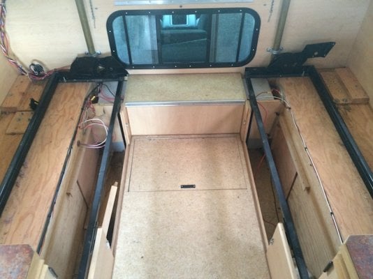
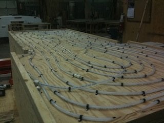
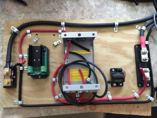
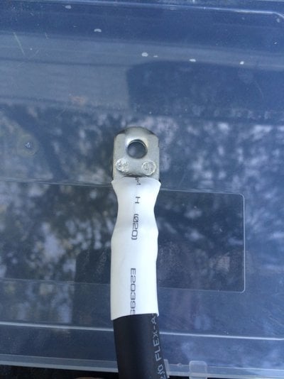
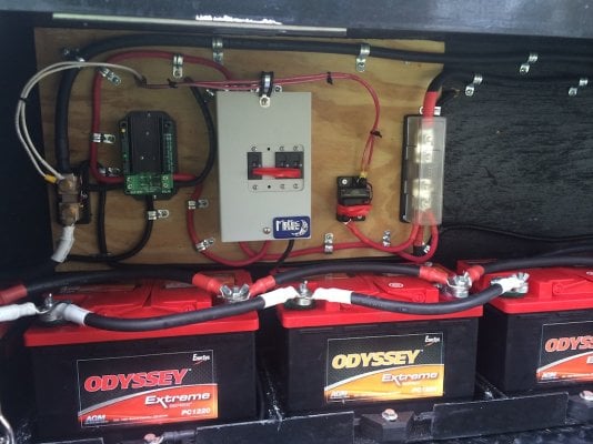
Working template for Solar DC configuration. The final configuration will be on 1/2 pressure treated

After reading everything I could find I purchased a Go Power Solar system then I found Jack and Bob's blog. I was headed for a cluster F...

Study their blogs before you buy anything, it will save you big $$, a lot of wasted time and ending up with Solar and a Genset

I found Bob through WTW. http://handybobsolar.wordpress.com and through HandyBob I found Jack Dananmayer at http://www.jackdanmayer.com.

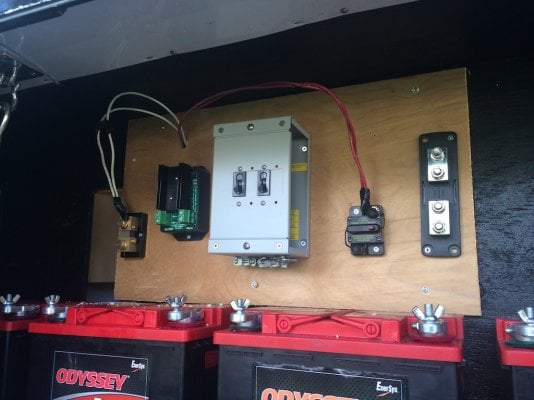
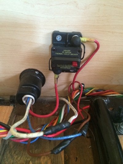
I have kept the best (and most expensive) of the Go Power, the panels and inverter and added a TM 2030 battery monitor and a SC-2030 Solar Charger both by Bogart Engineering along with a 500 amp shunt, Midnite Big Baby Box with two 30 amp CB to isolate the charger from the solar and battery.

I replaced the Go Power Class T fuse holder with a Blue Sea.

The biggest change comes in the wiring and location of the Solar Charger. The Go Power wiring is 10 AWG so the voltage drop over 15' would be + 5 volts and the charger is a panel mount which translates to a long way away from the batteries and more voltage drop. The net result is that the panels would never fully charge the house batteries.

I am putting an AM Solar combiner box on the roof to avoid paralleling the two 115 watt /15 amp panels with MC connectors on 10 AWG cables.

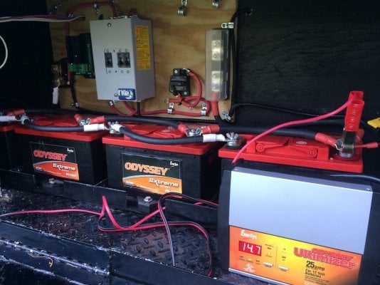
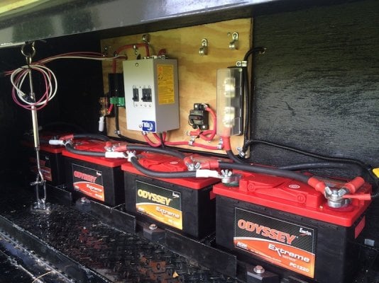
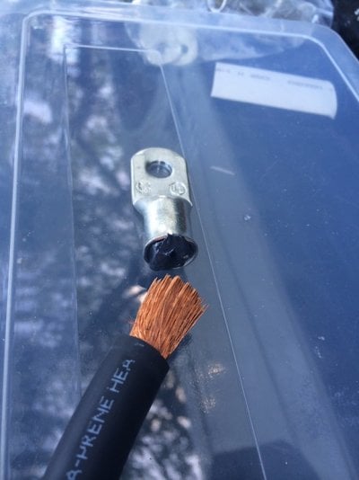
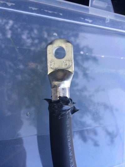
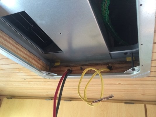
The 15' cable run from the combiner box to the charger mounted next to the batteries will be with 4AWG welding cables. The voltage drop should be in the area of 1.3 volts which is acceptable

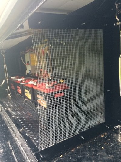
The battery bank is sized as close as I can to one amp of storage to one watt of power which translates to 280 amps of storage to 310 watts of solar capacity.

The wiring runs I will make myself.

.
 

Attachments

  • IMG_3325.JPG
    IMG_3325.JPG
    200.5 KB · Views: 164
Installed a 30 amp breaker on the 7 blade power recepticle so as to isolate the house batteries from truck batteries. The running and brake lights will continue to be direct.

.
 

Attachments

  • IMG_3329.jpg
    IMG_3329.jpg
    117.6 KB · Views: 130
I'm not trying to find work for you.....but....

sometime....in your spare time.....could you diagram that electrical circuitry....that sounds like a winner with all the isolations, protections and wire sizes...........

I'll just bet there are a ton of others who might just want to read that circuitry!

I'm just sayin :D
 
LOL. Well it is posted on http://www.jackdanmayer.com but for some reason the web site is down.

Update: Turns out there is an issue with Safari accessing his site but I went through Google and attached it.
http://www.jackdanmayer.com/rv_electrical_and_solar.htm

You have to scroll down on solar power and he has several diagrams and I picked the one for an inline inverter. My AC side is going to be modified from the diagram

I finally got in my terminal lugs and #4 welding wire.

I originally purchased 25 ' of # 6 because the Bogart engineering install instructions stated the terminal blocks on the solar charger would only take #6 but patience demonstrated it could handle a # 4.

That was a tough one because the voltage drop would have been too high with a # 6

I am still waiting on a battery temp sensor for the SC 2030 and have to find a cross connected telephone cable for the charger to talk to the monitor inside. Not sure where I am going to mount it yet.

I included a shot of the panel on my dining room table and had to explain to my 3 year old granddaughter why she could not "play with it".


.
 

Attachments

  • IMG_3344.JPG
    IMG_3344.JPG
    253 KB · Views: 191
  • Inline.gif
    Inline.gif
    51.1 KB · Views: 210
One thing that both Bob and Jack recommend is to never connect directly to the battery but to +- distribution terminals. I am not sure why and would appreciate any input on that or anything else.

In this case I am using the shunt and the T fuse holder which powers a 30 amp breaker for the camper so I can totally isolate power.
 
I like that "totally isolate the power"....going through an experience with another site...fishing and boats....isolating batteries...after a partial meltdown....

the cow and the barn door so to speak

The more accessible the switch, the better...as long as grand kids can't reach it...if that's possible ;)

I can't wait to see the camper sing and dance ...LOL
 
Ha! I sure hope it can sing and dance better than me.

I made the battery cables out of 2/0 welding cable which is the same size as the inverter cables which will be installed next week and paralleled the 4 batteries.

I temp mounted the solar charger panel but am still waiting on a temp sense and RJ14 cable then it will be bolted down. I mounted a spare 30 amp CB in the panel just in case and once everything is working I will mark the breakers. I will also install some wire grid to segregate this compartment off from UFO's from the rear portion.

The panel is 2' and the battery tray 4' so the panel was mounted equal distance from both +- posts. I made the positive cable then copied it for the - so they are matched in length to the respective distribution points. In the case of the + the T fuse and the - the shunt.

The camper is powered by truck batteries and will remain isolated from the house bank until I have installed the solar panels.

The IOTA converter's max DC output is 13.7 volts which is insufficient to fully charge the house battery bank so I have it on a Odyssey charger which has the correct charging profile for its AGM's.

Note: A word of caution. This is set up in a ventilated area with AGM batteries and chargers that do not exceed 15 volts but would be dangerous with standard lead acid or chargers that exceed 15 volts which some 2 wheel carts according to Odyssey do. Above 15 volts the pressure relief valve can open causing the battery to off gas hydrogen, oxygen and water

.
 

Attachments

  • IMG_3394.JPG
    IMG_3394.JPG
    245.6 KB · Views: 175
  • IMG_3390.JPG
    IMG_3390.JPG
    189.3 KB · Views: 152
When I had my boat I always had a lot of wiring problems so I was really glad to find Jack Danmayer's blog which has a lot of good advice on RV Solar wiring.

http://www.jackdanmayer.com/rv_electrical_and_solar.htm

He recommends tinned closed ended marine terminal lugs and a lot of anti-oxidant to prevent oxidization. Also making sure that ring hole is correctly sized for where it is going to be mounted.

I picked zinc battery terminals which are more efficient than lead and mine came with a positive 3/8 terminal and a 5/16 negative.

He recommends making one cable at a time and to add extra length in case the next set of batteries have different post locations.

Following his advice I would apply a liberal amount of antioxidant to the opening of the terminal and slide in approximately 3/4" of stripped cable.

I made two crimps, the first as close to the flange as possible and the next in the same proximity but with the cable turned 90 degrees.

I used a 10 ton manually operated hydraulic crimper ($30 on eBay) which was a little awkward at first but I got good tight connections.

I left the excess or added oxidant in the space between the cable insulation and heat shrink wrap to seal the cable and terminal lug.

After the first terminal was installed I would mount the lug, pull the cable to the next post and add one inch before I cut which give me extra cable as I mounted the positive to the inside over the battery and the negative on the outside.

Hopefully my experience of doing it what I think is right for the first time will be helpful to others.

.
 

Attachments

  • IMG_3379.jpg
    IMG_3379.jpg
    100.3 KB · Views: 146
  • IMG_3380.jpg
    IMG_3380.jpg
    89.6 KB · Views: 133
  • IMG_3382.jpg
    IMG_3382.jpg
    98.6 KB · Views: 146
Installed a wire mesh to prevent UFO's in the battery compartment but got to put a sleeve of some kind on the open side so I don't slice myself.
Solar Control Panel finished but battery bank /solar charger/battery monitor and camper will remain isolated until the Solar panels are installed.
Alaskan wires the refrigerator directly to the battery and thus the double camper positive and negative. I will change that down the road.
Moving to inside to install inverter, AC transfer relay and solar power cable runs.

.
 

Attachments

  • IMG_3458.JPG
    IMG_3458.JPG
    228.7 KB · Views: 135
  • IMG_3459.jpg
    IMG_3459.jpg
    118.6 KB · Views: 145
The maiden is still a virgin. My left knee which was originally messed up in Nam blew out. They say it needs to be replaced but I have elected not to and just try to loose more weight, strengthen my thigh muscles and get a second opinion.
Reminds me of the best laid plans of mice and men!
But I guess everything is in its time, my daughter made me a grandpa so I am saddling up to drive to Texas with Toby on the 23rd then weather permitting will try out my Rube Goldberg heater in Maine.
In the meantime I have continued to mod up with an AC install. The kicker was the wiring to power it and move solar power to the batteries.
I removed the rear fan then drilled two holes in the drivers side of the frame frame through the roof interior and the longitudinal beam supporting the cabinets then drilled vertically up and fed a 12/2 with ground 600V Romex through to power the AC and the 2AWG positive and negative welding cables for the solar panels.
It was dicey since it was about an 20 inch blind drill inside a space that is +-2 inches tall. It went well and I mounted the AC unit.
.
 

Attachments

  • IMG_3233.JPG
    IMG_3233.JPG
    130.4 KB · Views: 136
  • IMG_3612.JPG
    IMG_3612.JPG
    109.3 KB · Views: 151
  • IMG_3617.jpg
    IMG_3617.jpg
    123.3 KB · Views: 148
Hi BluesideUp,
the luck is with the hard-working they say in germany. I follow your thread since month´s and it is great which high tech camper you
are able to convert your alaskan in! Congratulations!
Restoring my Jayco i always dream Alaskan ! I am in a good contact with Don Wheat so i hope to find my way to Chehalis one day and a Alaskan will find his way to germany !

I don´t know if i find the correct words in my awful english but i wish you a good and fast recovery and improvement with your knee.
Keep on modifying. I love it !
 
Hello Manfred, good to see you on line. How is your project going? Your English is "alles goot" is my terrible german. I should be better since I grew up in Germany, living in Bad Homburg then Berlin when it was West Berlin. The project build is fun but terrible expensive in time and money
 
Well got my butt on the road for a month to shake out what I have done. Staying on the grid as I work my way out of Florida to Texas then leaving in a couple of days for PA and then onto ME then back to Miami in 3 weeks.
Once home I will install my solar panels and winter camp in Florida
 
Back
Top Bottom