Rusty
Senior Member
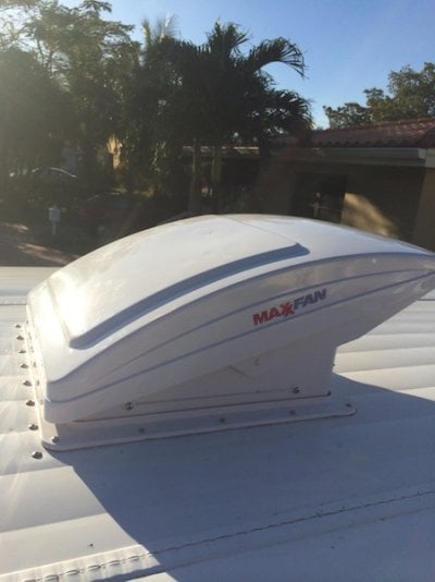
Nice fit....never enough air ")
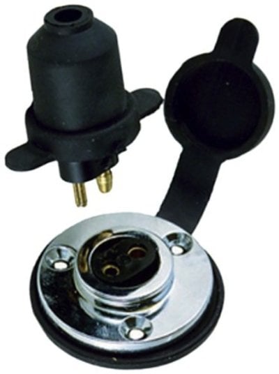
is that the 200#/1.76 cfm unit?
is that the 200#/1.76 cfm unit?
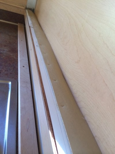
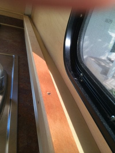
....no scratching, rubbing or buffingI am late in discovering your post and responding. By the way, the execution of your project is way beyond my skill level. But I found your pics and description extremely interesting and yes, some of your posts do indeed have particular relevance to us and our 8 year old CO Alaskan. I do have a comment regarding incorporating solar into the Alaskan experience. Four or five years ago I purchased a Kyocera 65 watt panel, Sunkeeper 6 charge controller by Morningstar and 20 feet of cable. I made a stand to set the panel in with the ability to adjust the angle as needed, a sturdy carrying box for the panel and a plug to plug into the camper outside plug-in. When we stop to camp, I unplug the line coming from the truck and plug in the panel cord and plug. I then move the panel around to where the best solar gain is. This setup has served us with all the power needed for our minimal needs. Most of the time this is the two fantastic fans, refrigerator fan and lights. Sometimes it also includes the furnace fan.BluesideUp said:When I extended the deck of the flatbed we moved the brake, position and backup lights however I soon noticed at night, especially in the rain with water on the rear view mirrors how cumbersome backing up in tight places could be.
I had kept the wiring for the headache rack backup light coiled under the bed after we cut the rack so I ran a splice to each side of the original backup light position and installed the original incandescent lights. They actually seem brighter than LED's.
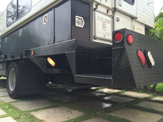
So we will see if four backup lights are better than two.
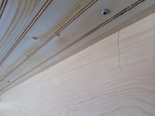
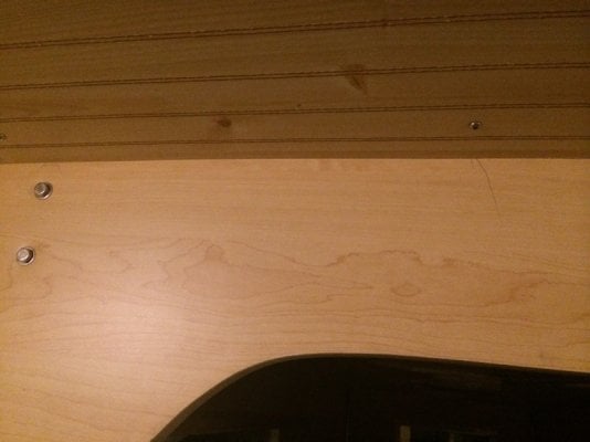
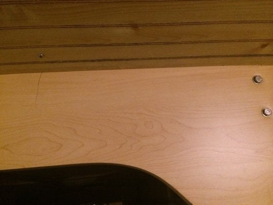
Note if you look closely under the rear brake light you can see a nice crease that attests to the level of my skills.
.